
Specifications


5-58 Menus and Commands
600561-A
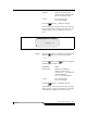
Figure 5-68 Target Dialog
Step 3 Press the button to select the current
parameter value and move to the next parameter.
— or —
Press the button or the button to toggle
between the parameter values in the following list.
Parameters Values
Coord The first field indicates the
type of cell (I for I/E Station, D
for Drive, S for Storage cell)
The second field indicates the
module number which can be
modified if expansion
modules are present (1 .. 4)
The third field indicates the
storage cell section (1 .. 4),
drive bay (1 .. 2), or IE station
number
The fourth field indicates the
column of the section (A .. E),
drive port (A .. B) or IE station
column
The fifth field indicates the
row of the column. (01 .. 12 for
half inch and DLT
coordinates)
(01 .. 18 for 8mm coordinates)
Element Indicates the element number
which corresponds with the
coordinate parameter
Accept Y to accept changes
N to reject changes
Press the button to confirm the changes.
Enter TARGET
Coord: S 01 2< A 01
OR Element: 00000
Accept : N
Note
The starting
address is
indicated by the
Coordinate or
Element
parameter. If
several cleaning
tapes are
inserted, the
Coordinate or
Element is
specified for the
first empty cell in
a group of
consecutive
empty cells.