743 - 221 Sewing unit for the automated sewing single-point darts with straight or curved seam form and for the sewing of pleats.
Anleitung, komplett Manual, complete 743 - 221 Inhalt Summary Bedienungstafel Operating table Bedienanleitung Aufstellanleitung Serviceanleitung Programmieranleitung Instructions for operating Installating instruction Instructions for service Instructions for programming Bauschaltplan Interconnection-diagramm 9870 743031 B 9870 743031 B Stromlaufplan Circuit-diagram 9850 743030 SK 9850 743030 SK Pneumatik Geräteplan Pneumatic circuit plan 0794 013225 0797 743012 0794 013225 0797 743012 Po
Foreword This instruction manual is intended to help the user to become familiar with the machine and take advantage of its application possibilities in accordance with the recommendations. The instruction manual contains important information on how to operate the machine securely, properly and economically. Observation of the instructions eliminates danger, reduces costs for repair and down-times, and increases the reliability and life of the machine.
General safety instructions The non-observance of the following safety instructions can cause bodily injuries or damages to the machine. 1. The machine must only be commissioned in full knowledge of the instruction book and operated by persons with appropriate training. 2. Before putting into service also read the safety rules and instructions of the motor supplier. 3. The machine must be used only for the purpose intended. Use of the machine without the safety devices is not permitted.
Contents Page: Part 4: Instructions for programming DA Microcontrol Cl. 743-221 . Program version: 743221A3 1. General . . . . . . . . . . . . . . . . . . . . . . . . . . . . . . . . . . . . . . . . . . . . . . . . . 3 2. 2.1 2.2 2.3 Description of the Controls Operator Controls on the Front Panel . . . . . . . . . . . . . . . . . . . . . . . . . . . . . . . . Operator Controls at the Controls . . . . . . . . . . . . . . . . . . . . . . . . . . . . . . . . . . Display . . . . . . . . . . . . . . . . .
1. General The MICROCONTROL controls of the DÜRKOPP ADLER 743-221 include the integrated comprehensive MULTITEST testing and monitoring system. A microcomputer assumes the control tasks, monitors the sewing process and signals operating faults and malfunctions. Special programs facilitate mechanical adjustments and make possible a rapid testing of the input and output elements without additional measuring apparatus. Errors and test results are shown in a 2 x 16 digit display.
2. Description of the Controls 2.
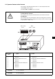
2.2 Operator Controls at the Controls The needle- and underthread monitors are activated with the DIP switch b417 at the controls. The dials b401 and b402 have no function. Caution Electric Current ! The switches may only be altered with the main switch turned off. ATTENTION ! The switches are only verified once after the sewing unit is turned on. After changing the switch setting turn the main switch off and on again or operate the " STOP " key.
2.3 Display The Microcontrol controls are equipped with a 2 x 16 digit display. It displays program number, sewing lengths, underthread reserve and piece counts. With operator errors or malfunctions the function sequence is interrupted and the cause shown by the corresponding error symbol. The operational readiness of the sewing unit is signaled by showing the current parameters in the display. The settings correspond to the last selected setting before being turned off.
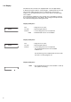
3. Description of the Function Keys 3.1 Selecting and Adjusting the Seam Length Three stored seam lengths can be selected via the L1, L2 and L3 keys. A change in the seam length can only be made before starting the feed procedure. – Select the stored seam length by pressing the L1, L2 or L3 key. The selected seam length is shown in the right half of the first line of the display. – If "L?" appears in the display a seam length was selected under which no valid value is stored.
3.4 Setting Parameter Values The set parameter values / seam lengthsare changed via the " + " or " - " key. – Press the " + " key. The parameter value / seam lengthsis increased. – Press the " - " key. The parameter value / seam lengthsis decreased. – Only in program 41 ! Press the " + " and " - " keys at the same time. The initial value for the underthread reserve is reset to 0000.
3.8 Securing at the Seam End End securing at the seam end is selected by pressing this key. The end securing is only conducted if it is activated with the " – – " key. Press the key. Securing through stitch condensation is selected. The LED is lit. Press the key. Securing through seam bar tacking is selected. The LED is off. 3.9 Securing Activation The selected securing at the seam beginning or at the seam end is activated by pressing this key. – Press the key.
4. Setting the Sewing and Testing Programs The sewing and testing programs are selected with the " Program " selection switch. – Set the " Program " switch to the desired program. – " Turn the main switch on " or press the " STOP " key. The selected program is activated. – If the " P? " message appears, an invalid program was set. (Exception in program 43. See there) Correct the setting and press the " STOP " key.
4.2 Sewing Program for Darts The program positions 10 ...29 are available for free programming of darts and pleats. The programming mode is activated by pressing the " P " key for minimum 3 seconds. The value shown is changed with the " + " and " - " keys. The value is immediately saved in nonvolatile memory. The next program step is called up with the " Σ " key. At the last program step the return to the 1st program step occurs by pressing the " Σ " key.
– Press the " Σ " key. Set the number of stitches for stitch condensation at the seam beginning. Setting range: 3 - 8 stitches Resolution: 1 stitch – Press the " Σ " key. Set the number of stitches for stitch condensation at the seam end. Setting range: 3 - 8 stitches Resolution: 1 stitch – Press the " Σ " key. Set the number of stitches for bar tacking at the seam beginning. Setting range: 3 - 5 stitches Resolution: 1 stitch – Press the " Σ " key.
4.4 Setting the Underthread Counter The underthread counter is set in program 41. The presetable decrementer monitors the underthread reserve. The decrementer works with the factor 10, this means, after every 10th stitch the preset value is decreased by 1. This is shown in the right half of the lower line of the display.
4.6 Stopping Point for the Function Sequence A sewing program with stopping points is run through in program 43. – Set the " Program " switch to " 43 ". – Press the " STOP " key. The sewing unit requests a reference run. – Press the " Σ " key. The reference run is conducted. – – – The display P? appears. Set the " Program " switch to the sewing program to be sewn with this testing program. Insert the table manually. The form set closes automatically. Press the " Σ " key.
4.8 Test of the Step Motor Drive Pulse Program 57 checks the step motor controller and the outputs of the step motor. – Set the " Program " switch to " 57 ". – Press the " STOP " key. The testing program is activated. The results appear.
4.10 Continuity Test Program 60 checks if the 24 V current supply supplies current with the output drivers turned off. Then program 60 checks all existing output elements, the output driver and the installation for continuity. – – Set the " Program " switch to " 60 ". Press the " STOP " key. The program is activated. Display V? S17 Explanation Short circuit in the installation or an output driver is defective. Interruption in the output element S17, in its installation or driver.
Key Function Symbol Display b814 Stitch condensation NA LED b815 Setting the counter Display b816 - Reserve - b817 - Reserve - b818 Blower from above / blower from the right LED / LED b819 Smoother LED / LED b820 A LED b821 Stitch condensation NE LED b822 Softstart LED b823 Minus Display b824 Plus Display b825 P display b826 Seam length through light barrier Display b827 L3 Display b828 L2 Display b829 L1 Display LED Function display H1b H2 H3c H4c H5b H6b
4.12 Checking the Input Elements Program 62 checks the input elements. – Set the "Program" switch to "62". – Press the "STOP" key. The program is activated. – Press the input element. The wiring diagram designation and the switching status of the input element appear in the display (e.g. "+B25"). The display changes when the switching status of any other input element is changed.
4.14 Selecting Output Elements Caution Risk of Injury ! During the function test do not reach into the running machine. Choose your position so that no injury is possible (e.g. Function test s17: Table back). The program checks the functioning of an output element. – Set the " Program " switch to " 64 ". – Press the " STOP " key. The program is activated. – Set the " Program " switch to the output element. – Press the " Σ " key. The selected output element is turned on. – Press the " Σ " key.
4.16 Positioning the Machine Head in the 1st Needle Position Program 67 positions the machine head in the 1st position (needle down). – Set the " Program " switch to " 67 ". – Press the " STOP " key. The program is activated. Display " SW? " Program sequence and description as in 4.15. Positioned is in the 1st position. 5.
6. Step Motor Output 1 2 5 3 6 4 Caution Electric Current ! Turn the main switch off ! The switches may not be adjusted while under current. The switches must be in the position shown ! 1 2 3 4 5 6 = = = = = = Step motor output Status displays Parameter switch Current selector switch Voltage selector Operation lamp 4 see Chapter 6.2 see drawing F 230 V ON / OFF 6.1 Status Displays LED 1 Undervoltage Shortfall in the supply voltage of more than 30 %.