743-221-01 Operating Manual
All rights reserved. Property of Dürkopp Adler AG and protected by copyright. Reproduction or publication of the content in any manner, even in extracts, without prior written permission of Dürkopp Adler AG, is prohibited.
Table of Contents 1 About this operating manual ..................................................... 3 1.1 1.2 1.3 1.4 1.5 1.5.1 1.5.2 Scope of application of the operating manual............................... 3 For whom is this operating manual?............................................. 3 Conventions of representation – Symbols and characters ........... 3 Other documents .......................................................................... 4 Liability.........................................
Table of Contents 6.2.2 6.2.3 6.3 6.3.1 6.3.2 6.3.3 6.4 6.5 6.5.1 6.6 6.7 6.7.1 6.7.2 6.7.3 6.8 2 Removing the transport securing devices................................... 49 Setting the working height .......................................................... 49 Attaching the machine parts removed for shipping..................... 50 Thread reel holder ...................................................................... 50 Holding device for the template set ..........................................
About this operating manual 1 About this operating manual The operating manual for the 743-221-01 sewing unit was compiled with the utmost care. It contains information and notes in order to make longterm and reliable operation possible. Should you notice any discrepancies or if you have improvement requests, then we would be glad to receive your feedback, chapter 5.8. Please regard the operating manual as part of the product and keep it in a safe place where it can be easily accessed.
About this operating manual Symbol/character • Meaning Lists are identified by bullet points. 1. Instructions are numbered and have to be performed in the specified order. 2. References to further information in this operating manual or other documents are identified by this symbol. Safety Important warnings for the user of the machine are specifically marked.
About this operating manual 1.5.1 Transportation Dürkopp Adler cannot be held liable for any damage during transport. Check the delivered product immediately after receiving it. Report any damage to the last transport manager. This also applies if the packaging is not damaged. Keep the machines, devices and packaging material in the condition they were at the time when the damage was identified. That secures any claims towards the transport company.
About this operating manual 6 Operating manual 743-221-01 version 01.
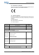
Performance description 2 Performance description The Beisler 743-221-01 is a sewing unit for the sewing of single pointed darts and pleats of straight or curved shape in trousers, skirts and the like. The sewing unit is equipped with a double lockstitch sewing machine class 935-271-710 with large horizontal hook, needle thread monitor and residual thread monitor for the hook thread. 2.
Performance description 2.2 Declaration of conformity The machine complies with the European regulations specified in the declaration of conformity or in the installation declaration. 2.3 Optional equipment By means of a flexible system of optional equipment the sewing unit can be equipped optimally and economically corresponding to the respective application. = Basic equipment = required equipment, alternatively = Optional equipment Order No.
Performance description 0794 013731 Working method workpiece take-up from the left bundle clamp, positioning table and smoother 0794 013333 Blower pipe from the top and the right 0794 013444 Positioning table when using in-house bundle clamp carriage 0797 003031 Pneumatic connection kit Operating manual 743-221-01 version 01.
Performance description 2.4 Technical data Technical data 743-221-01 Sewing stitch type 301/double lockstitch Number of needles 1 Needle system 134 serv 7 Needle size [Nm] 90 Max. number of stitches (programmable) [min-1] 4800 Stitch length (programmable) [mm] 0.5-3 Stitch condensing (programmable) [mm] Number of stitches [n] (programmable) 1-10 Number of bartack stitches [n] (programmable) 0-5 Max. stitch length [mm] 150 Max.
Safety instructions 3 Safety instructions This section contains basic instructions for your safety. Read the instructions carefully before setting up or operating the machine. Make sure to follow the information included in the safety instructions. Failure to do this can result in serious injury and in damage to the machine. 3.1 Basic safety instructions The machine may only be used as described in this operating manual. The operating manual must be available at the machine's location at all times.
Safety instructions Work on electrical equipment may only be carried out by qualified specialists. Only authorized persons may work on the machine. Every person who works on the machine must have read the operating manual first. Operation Inspect the machine while in use for any externally visible damage. Inter- rupt your work if you notice that the machine has been altered. Report any alterations to your supervisor. A damaged machine must not be operated any more.
Safety instructions Symbols In the case of dangers to personnel, the following symbols indicate the type of hazard: Symbol Type of danger General danger Danger due to electric shock Danger due to sharp objects Danger due to crushing Examples Examples of the layout of the warnings in the text: DANGER Type and source of the danger Consequences in the event of noncompliance Measures for avoiding the danger This is what a warning looks like for a hazard that will result in serious injury or even death i
Safety instructions CAUTION Type and source of the danger Consequences in the event of noncompliance Measures for avoiding the danger This is what a warning looks like for a hazard that could result in moderate or minor injury if the warning is not complied with. CAUTION Type and source of the danger Measures for avoiding the danger This is what a warning looks like for a hazard that could result in environmental damage if not complied with.
Machine description 743-221-01 4 Machine description 743-221-01 The Beisler 743-221-01 is a sewing unit for the sewing of single pointed darts and pleats of straight or curved shape in trousers, skirts and the like. The correct operating principle involves a sequence of different steps and requires precise knowledge of all operating controls. 4.1 Sewing unit 743-221-01 The illustration below shows the sewing unit 743-221-01. Fig.
Machine description 743-221-01 4.2 Software description At this point only a short overview of the operating panel with its keys and corresponding functions is given. Fig. 2: Operating Panel OP 3000 ཱི ི ཱ (1) - Display (2) - Numeric keys (3) - Escape key (4) - OK key The settings of the control unit are effectuated via the operating panel OP3000.
Operating the sewing unit 5 Operating the sewing unit The Beisler 743-221-01 is a sewing unit for the sewing of single pointed darts and pleats of straight or curved shape in trousers, skirts and the like. The correct operating principle involves a sequence of different steps and requires precise knowledge of all operating controls. 5.1 Switching on and off ATTENTION! Caution: Danger of injury! Do not reach into the area of moving machine parts. Fig.
Operating the sewing unit 5.2 Threading in the needle thread ATTENTION! Caution: Danger of injury! Turn off the main switch. Thread the needle thread only with the sewing unit switched off. Fig. 4: Threading in the needle thread Thread the needle thread as shown in the picture above. 18 Operating manual 743-221-01 version 01.
Operating the sewing unit 5.3 Adjusting the needle-thread tension Fig. 5: Adjusting the needle thread tension (1) - Main tensioner Main tension The main tensioner (1) should generate the adequate needle thread tension for the particular material and needle thread • Turn the knurled nut accordingly. Turn the knurled nut in clockwise direction = Increase the tension Turn the knurled nut in counter-clockwise direction = Decrease the tension Operating manual 743-221-01 version 01.
Operating the sewing unit 5.4 Needle thread monitor ATTENTION! Caution: Danger of injury! Turn off the main switch before threading in the needle. A restart is only possible after switching the main switch off and on again. Fig. 6: Needle thread monitor (1) - Thread monitor At needle thread rupture, a rupture message will appear on the display and the machine stops. 1. Turn the machine off the main switch. 2. Remove the unfinished workpiece. 3. Thread in the thread again, 5.
Operating the sewing unit 5.5 Setting the thread regulator ATTENTION! Caution: Danger of injury! Turn off the main switch. Adjust the thread regulator only with the sewing unit switched off. The thread regulator (2) controls the quantity of thread required for the stitch formation. The thread regulator has to be precisely adjusted for an optimum sewing result.
Operating the sewing unit Adjustment instruction: The thread regulator's (2) is correctly adjusted if: The thread take-up spring (1) is pulled down about 1 mm from its upper final position, when the thread loop (6) passes the maximum hook breadth. The length of 1 mm is an approximative guide value. Depending on the tension of the thread take-up spring it may be higher or lower. 5.6 Winding on the hook thread ATTENTION! Caution: Danger of injury! Turn off the main switch.
Operating the sewing unit 6. Swivel the winder clip (4) against the bobbin. 7. Set the bobbin thread tension (1). Wind on the hook thread with minimum tension. 8. Turn the main switch on. 9. Start the sewing process. After reaching the set bobbin filling level the winder stops automatically. For the setting of the bobbin filling level, see Service Instructions. Operating manual 743-221-01 version 01.
Operating the sewing unit 5.7 Changing the bobbin ATTENTION! Caution: Danger of injury! Turn off the main switch. Change the hook thread bobbin only with the machine switched off. ATTENTION! Material damage For a trouble-free functioning of the residual thread monitor, clean the lenses of the reflecting light barrier (2) after each bobbin change with a soft cloth. Fig.
Operating the sewing unit 7. Insert the upper bobbin case (7) back into the hook, make sure the bobbin case flap (1) snaps into place. 8. Turn on the main switch. 9. Start a new sewing cycle. 5.7.1 Counter for the hook thread reserve The remaining number of hook thread stitches is indicated on the display, see 5.14 Setting the control unit, p. 34. Resetting 1. Select the symbol hook thread counter with the arrow keys. 2. Effectuate a long stroke on the “OK” key.
Operating the sewing unit The light beam transmitted by the light barrier (1) is reflected by the exposed reflecting surface (2) of the bobbin hub (3). The display of the control unit shows a corresponding message. The seam is safely finished with the thread remaining in the reserve groove. ATTENTION! Caution: Danger of injury! Turn off the main switch. Change the hook thread bobbin only with the machine switched off. Changing the bobbin 1. Turn off the main switch. 2.
Operating the sewing unit 5.9 Setting the hook thread tension The necessary hook thread tension is generated by the tension spring (1). ATTENTION! Caution: Danger of injury! Turn off the main switch. Adjust the tension spring (1) only with the sewing unit switched off. Fig. 11: Setting the hook thread tension ཱ ི (1) - Tension spring (2) - Adjusting screw ི (3) - Upper bobbin case 1. Insert a full bobbin in the upper bobbin case (3). 2. Thread in the hook thread. 3.
Operating the sewing unit 5.10 Changing the needle ATTENTION! Caution: Danger of injury! Turn off the main switch. The needle may only be changed with the sewing machine switched off. Fig. 12: Changing the needle ཱ ི (1) - Screw (2) - Needle bar (3) - Groove 1. Loosen screw (1) and remove the needle. 2. Push the new needle into the drill-hole of the needle holder (2) as far as it will go. Attention! Seen from the machine operator's side the needle scarf (3) should point to the right, i. e.
Operating the sewing unit 5.11 Changing the template set A template set adapted to the desired sewing shape has to be inserted. It allows for the sewing of straight and curved darts, pleats or, on request, also special customer requirements can be realized, 2.3 Optional equipment, p. 8. ATTENTION! Caution: Danger of injury! Turn off the main switch. The template set may only be changed with the sewing machine being switched off. Fig.
Operating the sewing unit 6. Position the hold-down cylinder (4) with the guide roller on the control cam (3). 7. Slide the template set to the right as far as it will go. 5.12 Working range, angle and length The dart depth depends on: • the individual template set • the dart length • the position of the folding table The folding table can be continuously adjusted from 0-10°. The dart depths for different inclinations and lengths are indicated in the diagrams.
Operating the sewing unit The angle is set. 4. Pull out the folding table. . Setting the length Maximum dart length 150 mm. The seam length is regulated by programming it in the main menu or by the light barrier. The variant to be used, light barrier or set value, can be selected in the main menu, 5.14 Setting the control unit, p. 34. With transparent sewing material it is recommended to regulate the seam length by programming. Example Template set, straight darts Fig.
Operating the sewing unit 5.13 Setting the insertion depth of the folding table ATTENTION! Caution: Danger of injury! Turn off the main switch. The insertion depth may only be set or altered with the sewing machine being switched off. The first needle entry in the material should be as close as possible to the fold edge. In order to achieve an evenly slim dart point with material of varied thickness, the machine is equipped with a fine adjustment.
Operating the sewing unit Altering the insertion depth 1. Release the lever (4). 2. Slide the folding table on its guiding a little to the front. 3. Turn the adjustment knob (2) to the desired insertion depth (until it stops). 4. Slide the folding table back to the rear. The adjustment knob (3) has to abut on the stop (1). 5. Tighten the lever (4) again. Operating manual 743-221-01 version 01.
Operating the sewing unit 5.14 Setting the control unit At this point only the settings needed for sewing will be mentioned. Additional settings on the technician level are described in the Service Instructions. The control unit is operated via the operating panel OP3000, 4.2 Software description, p. 16. After switching on the machine the firmware and software versions will briefly be displayed. After this start the reference run by pressing the “OK“ key, p. 17.
Operating the sewing unit Main menu - Top line Hook thread counter Display of the number of stitches (in intervals of 10 stitches) that can still be sewn with the bobbin. Resetting the hook thread counter: • Long stroke on the “OK” key Seam counter Display of the seam segments that have been sewn so far Resetting the seam counter: • Long stroke on the “OK” key Submenu Access to the submenu with the “OK” key Main menu - Bottom line In the bottom line additional functions are activated or disabled.
Operating the sewing unit 5.14.2 Functions in the submenu Submenu structure Symbol Menu item Settings Speed Soft Start Activated, Stitches, Speed Advance Length, Speed Seam Begin Lock type, Stitches, Speed, Stitchlength Seam Between Lock type, Stitches, Speed, Stitchlength, Start at Seam End Lock type, Stitches, Speed, Stitchlength Thread Chain Length, Speed Stacker TimeTillStart, TimeTillStop Navigating in the submenu Fig.
Operating the sewing unit Changing the val- 5. Change the value for the setting by using the numerical keys or the ue arrow keys (▼,▲). 6. Confirm the desired value with the “OK” key. The value is applied and memorized for the particular program. Return 7. Use the arrow key ◄ to return to the previous level in the submenu. 8. Use the escape key to return to the main menu.
Operating the sewing unit Menu item Seam Begin Settings for tacks/stitch condensing at seam beginning Symbol Setting Explanation Range of values Lock Type Choose between tack and stitch condensing with the “OK” key: • Tack: display shows ““ • Stitch condensing: blank display Tack/ stitch condensing Stitches Number of stitches with tack/stitch condensing 1–9 Speed Number of revs for the sewing speed when sewing the tack/stitch condensing 500 – 3000 Stitchlength Stitch length of the stitch con
Operating the sewing unit Menu item Thread Chain Settings for a thread chain at seam end Symbol Setting Explanation Range of values Length Length of the thread chain in mm 8 – 25 Speed Number of revs for the sewing speed when sewing the thread chain 500 – 3000 Menu item Stacker Settings for the stacker Symbol Setting Explanation Range of values TimeTillStart Time span in milliseconds after the seam end, before the smoother is activated.
Operating the sewing unit 5.15 Sewing In order to start sewing, certain requirements have to be fulfilled. Below you will find the description of a typical sewing process. Before sewing start, all dart lengths have to be marked on the folding plate (1) with adhesive tape (flat and as thin as possible). ATTENTION! Caution: Danger of injury! Only mark the dart length with the sewing machine being switched off. ATTENTION! Material damage Do not slide in the folding table without sewing material on it.
Operating the sewing unit 5. Align the cut edges with the right hand to come on top of each other. 6. Adjust the notch for the dart length exactly at the rear edge of the folding plate. 7. Fix the workpiece by holding it with the right hand and slide in the folding plate. The workpiece is kept in place by the template set. The folding plate slides back. The sewing process is carried out. Operating manual 743-221-01 version 01.
Operating the sewing unit 5.16 Maintenance of the sewing unit ATTENTION! Caution: Danger of injury! Turn off the main switch. The maintenance of the sewing machine must only be carried out when the machine is switched off. 5.16.1 Swinging up the machine head. ATTENTION! Caution: Danger of injury! Turn off the main switch. Swing the machine head up only when the sewing unit is switched off. For maintenance work the machine head can be swung up. Fig.
Operating the sewing unit 3. Carefully swing up the machine head with the handle (3) and make it rest against the support. The machine's gravity center keeps it in position. 4. Swing back the machine in the same way. 5.16.2 Cleaning A clean sewing unit is a trouble-free sewing unit. Daily Fig. 22: Daily cleaning Cleaning (1) - Drain screw 1. Remove all fluff balls. 2. Clean the lenses of the light barrier with a soft cloth. 3. Check the water level in the pressure regulator.
Operating the sewing unit Depending on Fig. 23: Cleaning as the need arises the amount of fluff ཱ (2) - Motor fan grille Clean the motor fan grille (2). 5.16.3 Oil lubrication ATTENTION! Caution: Danger of injury! Oil can cause skin rashes. Avoid a longer skin contact with the oil. After contact wash yourself thoroughly. ATTENTION! Environmental hazards: The handling and disposal of mineral oils is subject to legal regulations. Deliver used oil to an authorized collecting station.
Operating the sewing unit To lubricate the sewing unit use only DA -10 lubricating oil or an equivalent oil with the following specifications: Viscosity at 40° C:10 mm²/s Ignition point:150° C DA-10 lubricating oil is available from the DÜRKOPP ADLER AG sales offices under the following parts numbers: 250-ml container: 9047 000011 1-liter container 9047 000012 2-liter container 9047 000013 5-liter container 9047 000014 hook lubrication 1. Swinging up the machine head as described. 2.
Operating the sewing unit Machine head lubrication 1. The oil level in the oil reservoir (2) must not drop below the marking min. 2. If necessary, fill in oil through the drill-hole (1) in the inspection glass up to the marking max. Fig. 25: Oil reservoir 2 - machine head ཱ (1) - Drill-holes 46 (2) - Oil reservoir 2 Operating manual 743-221-01 version 01.
Installation 6 Installation In the following, the steps are listed in chronological order. The structure of the chapter follows this order. The manufacturer will not be held liable for damage resulting from improper use. WARNING Danger of injury due to insufficient technical knowledge During the installation of the machine, insufficient technical knowledge can lead to serious injuries. The machine should be installed ONLY by trained personnel.
Installation 6.2 Installing the sewing unit 6.2.1 Transportation . CAUTION Risk of injury due to incorrect transportation! Do NOT lift the sewing unit at the table tops. ALWAYS use an elevating platform truck or a forklift CAUTION Risk of injury due to unstable footing! Before putting the sewing unit into operation screw in the castors until the unit attains a secure standing. Lifting the sewing unit • Only with an elevating platform truck or a forklift.
Installation 6.2.2 Removing the transport securing devices Before installing the sewing unit, you have to remove all the securing devices. All movable parts have to be unlocked: • Positioning table • Sewing drive • Smoother and bundle clamp • Positioning table If the sewing unit has to be transported to another place, you have to attach the securing devices again. 6.2.3 Setting the working height The working height is adjustable between 850 and 1250 mm (measured to the upper edge of the table plate).
Installation 6.3 Attaching the machine parts removed for shipping Some parts of the machine had to be removed or shifted in their position for shipment. These parts have to be attached correctly before start of work. 6.3.1 Thread reel holder The thread reel holder is loosely added for shipment. In order to connect the machine to the power supply from the top, the connection cable can be run through the tube (2) of the thread reel holder.
Installation 6.3.2 Holding device for the template set Fig. 29: Holding device ཱ (1) - Holding device (2) - Template set During the transport the holding device (1) for the template set (2) is underneath the table top. 1. Remove the fastening screws. 2. Rotate the holding (1) device by 180°. 3. Attach the fastening screws again. 6.3.3 Attaching the operating panel OP 3000 Fig. 30: Fixation operating panel OP 3000 ཱ (1) - Control panel (2) - Angle 1. Attach angle (2). 2.
Installation 6.4 Electrical connection DANGER Risk of injury due to electric power! Unprotected contact with electric power can cause dangerous injuries to life and limb. All work on the electrical equipment may ONLY be carried out by qualified electricians or other appropriately trained persons. ALWAYS disconnect the power plug before carrying out work at the electrical equipment. Connection Fig. 31: Connection control panel the control panel ཱ (1) - Plug (2) - Screws 1.
Installation 6.5 Pneumatic connection For the operation of the pneumatic components the sewing unit has to be supplied with anhydrous compressed air. ATTENTION Material damage! For a trouble-free function of the pneumatic control procedures the compressed air supply must operate as follows: Even at the moment of the highest air consumption the minimum operating pressure (2) must not drop below 6 bar. ATTENTION Material damage! No oil-bearing compressed air must be fed from the compressed air line.
Installation Fig. 32: Pneumatic connection ཱ (1) - Blowing pressure (2) - Operating pressure To adjust the pressure lift the corresponding rotary handle and twist it. • Turning in clockwise direction = the pressure is increased • Turning counter-clockwise = the pressure is reduced 6.5.1 Oil lubrication ATTENTION Caution: Danger of injury! Oil can cause skin rashes. Avoid a longer skin contact with the oil. After contact wash yourself thoroughly.
Installation To lubricate the sewing unit use only DA -10 lubricating oil or an equivalent oil with the following specifications: Viscosity at 40° C: 10 mm²/s Ignition point: 150° C DA -10 lubricating oil is available from the DÜRKOPP ADLER AG sales offices under the following parts numbers: 250 ml container: 9047 000011 1-liter container 9047 000012 2-liter container 9047 000013 5-liter container 9047 000014 Hook lubrication 1. Swing up the machine head as described. 2.
Installation Machine head lubrication 1. The oil level in the oil reservoir (1) must not drop below the marking min. 2. If necessary, fill oil through the drill-holes in the inspection glass up to the marking max. Fig. 34: Oil reservoir 2 - machine head ཱ (1) - Oil reservoir 2 (2) - Drill-holes 6.6 Putting into operation After completion of the installation work a sewing test should be made. • Plug in the mains plug.
Installation 6.7 Installation of the software 6.7.1 General information Loading a specific sewing software in the DAC classic control unit is possible with the help of the “Programmed Dongle”. The “Programmed Dongle” has a label indicating the machine class and the software version. Such a loading (booting) may be used in order to provide a single DACclassic control unit with a sewing software (first installation) or to install a newer machine software (update).
Installation 6.7.2 Loading the program ATTENTION Material damage! During the loading process do not remove the dongle and do not switch off the machine (otherwise you will destroy the software). Fig. 35: Connecting the dongle (1) - Dongle ཱ (2) - Plug-in position 1. Turn off the main switch. 2. Insert the dongle (1) into the plug-in position (2) of the control unit. 3. Turn the main switch on. The Software will be loaded. The loading process takes less than 60 seconds. 4. Turn off the main switch.
Installation 6.7.3 Dongle-Update via Internet ATTENTION Material damage! When transferring the machine software onto the dongle, it will first be deleted (formatted). The programs (sequences, parameters) saved on the dongle will then be deleted. If still needed, please make a backup of the files into a computer (desktop, notebook). The required software “Dongle Copy” is available in the “Download Area”. Dongles can be updated by means of Internet.
Installation 60 Operating manual 743-221-01 version 01.
Subject to design changes - Printed in Germany - © Dürkopp Adler AG - Operating Manual - 0791 743060 EN - 01.0 - 09/2013 DÜRKOPP ADLER AG Potsdamer Str.190 33719 Bielefeld Germany Phone +49 (0) 521 925 00 E-Mail: service@duerkopp-adler.com www.duerkopp-adler.