NuIPC / NuDAQ cPCI-7300A & PCI-7300A 80MB Ultra-High Speed 32-CH Digital I/O Boards User’s Guide Recycle Paper
Copyright 2002 ADLINK Technology Inc. All Rights Reserved. Manual Rev 2.22: July 16, 2002 Part No.: 50-11106-100 The information in this document is subject to change without prior notice in order to improve reliability, design and function and does not represent a commitment on the part of the manufacturer.
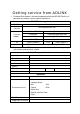
Getting service from ADLINK • Customer Satisfaction is the most important priority for ADLINK Tech Inc. If you need any help or service, please contact us. ADLINK Technology Inc. Web Site http://www.adlinktech.com Sales & Service Service@adlinktech.com NuDAQ + USBDAQ nudaq@adlinktech.com Automation automation@adlinktech.com Technical Support TEL Address NuIPC nuipc@adlinktech.com NuPRO / EBC nupro@adlinktech.com +886-2-82265877 FAX +886-2-82265717 9F, No.
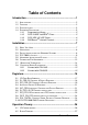
Table of Contents Introduction...............................................................................1 1.1 1.2 1.3 1.4 APPLICATIONS............................................................................................... 2 FEATURES ..................................................................................................... 2 SPECIFICATIONS ........................................................................................... 3 SOFTWARE SUPPORTING.................................
4.3 DIGITAL I/O D ATA FLOW .............................................................................28 4.4 INPUT FIFO AND OUTPUT FIFO ................................................................29 4.5 BUS-MASTERING DMA ...............................................................................30 4.6 SCATTER /GATHER DMA.............................................................................31 4.7 CLOCKING MODE ..................................................................................
5.19 5.20 5.21 5.22 5.23 5.24 5.25 5.26 5.27 5.28 _7300_DO_DMA_STATUS......................................................................63 _7300_DO_DMA_ABORT .......................................................................63 _7300_DO_PG_START...........................................................................64 _7300_DO_PG_STOP ............................................................................65 _7300_DI_TIMER ......................................................................
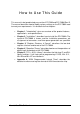
How to Use This Guide This manual is designed to help you use the cPCI-7300 and PCI-7300A Rev.B. The manual describes how to modify various settings on the PCI-7300A card to meet your requirements. It is divided into five chapters: • Chapter 1, "Introduction", gives an overview of the product features, applications, and specifications. • Chapter 2, "Installation", describes how to install the PCI-7300A.
1 Introduction The cPCI/PCI-7300A is cPCI/PCI form factor ultra-high speed digital I/O card, it consists of 32 digital input or output channel. High performance designs and the state-of-the-art technology make this card to be ideal for high speed digital input and output applications. The cPCI/PCI-7300A performs high-speed data transfers using bus mastering DMA and scatter/gather via 32-bit PCI bus architecture. The maximum data transfer rates can be up to 80MB per second.
1.1 Applications • Interface to high-speed peripherals • High-speed data transfers from other computers • Automated test equipment (ATE) • Electronic and logic testing • Interface to external high-speed A/D and D/A converter • Digital pattern generator • Waveform and pulse generation • Parallel digital communication 1.
1.3 Specifications ♦ Digital I/O (DIO) • Numbers of Channel: 32 TTL compatible inputs and/or outputs • Device: IDT 74FCT373 • I/O Configurations: 16 DI & 16 DO 32 DI 32 DO ♦ Input Voltage: • Low: Min. 0V; Max. 0.8V • High: Min. +2.0V ♦ Input Load: • Terminator OFF: Low: +0.5V @ ±20 mA High: +2.7V @ ±1 mA max. • Terminator ON: Termination resistor: 110 Ohms Termination voltage: 2.9V Low: +0.5V @ ±22.4mA High: +2.7V @ ± 1mA max. ♦ Output Voltage: • Low: Min. 0V; Max. 0.5V • High: Min. +2.
• Mode: Bus Mastering DMA with Scatter/Gather • Data Transfers: 8/16/32-bit input or output (programmable) ♦ DMA Transfer count: • 2M double words (8M bytes) for non-chaining mode DMA • No limitation for chaining mode (scatter/gather) DMA ♦ Max.
1.4 Software Supporting ADLINK provides versatile software drivers and packages for users’ different approach to built-up a system. We not only provide programming library such as DLL for many Windows systems, but also provide drivers for software ® TM TM TM packagesTM such as TM LabVIEW , HP VEE , DASYLab , InTouch , InControl , ISaGRAF , and so on. All the software options are included in the ADLINK CD. The non-free software drivers are protected with serial licensed code.
1.4.3 PCIS-VEE: HP-VEE Driver The PCIS-VEE includes the user objects, which are used to interface with HP VEE software package. PCIS-VEE supports Windows 95/98/NT. The HP-VEE drivers are free shipped with the board. You can install and use them without license. For detail information about PCIS-VEE, please refer to the user’s guide in the CD. (\\Manual_PDF\Software\PCIS-VEE) 1.4.
2 Installation This chapter describes how to install the cPCI/PCI-7300A. At first, the contents in the package and unpacking information that you should be careful are described. Because the PCI-7300A is following the PCI design philosophy, it is no more jumpers and DIP switches setting for configuration. The Interrupt and I/O port address are the variables associated with automatic configuration, the resource allocation is managed by the system BIOS.
2.2 Unpacking Your cPCI/PCI-7300A card contains sensitive electronic components that can be easily damaged by static electricity. The card should be placed on a grounded anti-static mat. The operator should be wearing an anti-static wristband, grounded at the same point as the anti-static mat. Inspect the card module carton for obvious damage. Shipping and handling may caus e damage to your module. Be sure there are no shipping and handling damages on the module before processing.
2.4 PCI-7300A's Layout Figure 2.
Figure 2.
2.5 Hardware Installation Outline PCI configuration The PCI cards (or CompactPCI cards) are equipped with plug and play PCI controller, it can request base addresses and interrupt according to PCI standard. The system BIOS will install the system resource based on the PCI cards’ configuration registers and system parameters (which are set by system BIOS). Interrupt assignment and memory usage (I/O port locations) of the PCI cards can be assigned by system BIOS only.
2.6 Connector Pin Assignment The PCI-7300A comes equipped with one 100-pin SCSI type connector (CN1) located on the rear mounting plate. The pin assignment of CN1 is illustrated in the figure 2.2. Legend: Pins Signal Name Signal Type Signal Direction 1…50 GND GND 51..66 PB15…PB0 DATA I/O 67 DOACK CONTROL I 68 DOREQ CONTROL O 69 DOTRIG CONTROL I 70…73 AUXDO3…0 DATA O 85..
PA0 PA1 PA2 PA3 PA4 PA5 PA6 PA7 PA8 PA9 PA10 PA11 PA12 PA13 PA14 PA15 DI_TRG DI_REQ DI_ACK AUXI0 AUXI1 AUXI2 AUXI3 TERMPWR TERMPWR TERMPWR TERMPWR AUXO0 AUXO1 AUXO2 AUXO3 DO_TRG DO_REQ DO_ACK PB0 PB1 PB2 PB3 PB4 PB5 PB6 PB7 PB8 PB9 PB10 PB11 PB12 PB13 PB14 PB15 100 99 98 97 96 95 94 93 92 91 90 89 88 87 86 85 84 83 82 81 80 79 78 77 76 75 74 73 72 71 70 69 68 67 66 65 64 63 62 61 60 59 58 57 56 55 54 53 52 51 50 49 48 47 46 45 44 43 42 41 40 39 38 37 36 35 34 33 32 31 30 29 28 27 26 25 24 23 22 21 20 19
2.7 Wiring and Termination Transmission line effects and environment noise, particularly on clock and control lines, can lead to incorrect data transfers if you do not take care when running signal wires to and from the devices. Take the following precautions to ensure a uniform transformation line and minimize noise pickup: 1. Use twisted-pair wires to connect digital I/O signals to the device. Twist each digital I/O signal with a GND line. In PCI-7300A, 50 signals are used as GND. 2.
2.8 Daughter Board Supporting The cPCI/PCI-7300A can be connected with two daughter boards: DIN-100S or DIN-502S. The functionality and connections are specified as follows. 2.8.1 Connect with DIN-100S The DIN-100S is a direct connection for the add-on card that is equipped with SCSI-100 connector. User can connect this daughter board by a 100-pin SCSI type cable (ACL-102100) to the cPCI/PCI-7300A. It is suitable for the applications of 32-bit digital input or 32-bit digital output. 2.8.
3 Registers In this chapter, the registers’ format of the cPCI/PCI-7300A is described. Please note that the registers’ map of the PCI-7300A Rev.B is different from the PCI-7300A Rev.A This information is quite useful for the programmers who wish to handle the card by low-level programming.
3.1 I/O Port Base Address The registers of the cPCI/PCI-7300A are shown in Table 3.1. The base address of these registers is als o assigned by the PCI P&P BIOS. The assigned base address is stored at offset 18h of the PCR. Therefore, users can read the PCR to know the base address by using BIOS function call. Note that the cPCI/PCI-7300A registers are all 32 bits. Users should access these registers by 32 bits I/O instructions.
3.2 DI_CSR: DI Control & Status Register Digital input control and status checking is done by this register. Address: BASE + 00 Attribute: READ/WRITE Data Format: Bit # 3~0 Bit # 7~4 Bit # 11~8 Bit # 15~12 Bit # 31~16 DI_HND_SHK 0 DI_FIFO_FULL Don’t Cared DI_CLK_SEL PA_TERM_OF DI_WAIT_TRI F G DI_OVER DI_FIFO_CLR - DI_32 -- (1) DI_EN DI-FIFO_EMPTY (1) This bit is different between Rev.A and Rev.B.
DI_FIFO_CLR (R/W) 0: No effect 1: Clear digital input FIFO. If both PORTA and PORTB are configured as inputs, both FIFO will be cleared. Always get 0 when read. DI_OVER (R/W) 0: DI FIFO does not full during input sampling 1: DI FIFO full during input sampling, some input data was lost, write “1” to clear this bit DI_FIFO_FULL (RO) 0: DI FIFO is not full 1: DI FIFO is full DI_FIFO_EMPTY (RO) 0: DI FIFO is not empty 1: DI FIFO is empty 3.
DO_WAIT_NAE (R/W) 0: do not wait output FIFO not almost empty flag 1: delay output data until FIFO is not almost empty PAT_GEN(R/W) 0: pattern generation disable (FIFO data do not repeat during data output) 1: pattern generation enable (FIFO data repeat themselves during data output) DO_WAIT_TRIG (R/W) 0: delay output data until DOTRIG is actived 1: start output data immediately PB_TERM_OFF (R/W) 0: PORTB terminator ON 1: PORTB terminator OFF PG_STOP_TRIG (R/W) 0: no effect 1: Stop pattern generation when D
BURST_HNDSHK (R/W) 0: disable burst handshaking mode 1: enable burst handshake mode * Note: This bit is for Rev.B only. 3.4 Auxiliary Digital I/O Register Auxiliary 4-bit digital inputs and 4 -bit digital outputs Address: BASE + 08 Attribute: READ/WRITE Data Format: Bit # 3~0 DO_AUX_3 Bit # 7~4 DI_AUX_3 Bit # 31~8 Don’t Cared DO_AUX_2 DI_AUX_2 DO_AUX_1 DI_AUX_1 DO_AUX_0 DI_AUX_0 This auxiliary digital I/O is controlled by porgram I/O only. DO_AUX_3 ~ DO_AUX_0 (R/W) 4-bit auxiliary output port.
T2_EN (R/W) 0: Disable Timer2 interrupt 1: Interrupt CPU on falling edge of Timer 2 output AUXDI0_INT (R/W) 0: AUXDI does not generate interrupt 1: AUXDI interrupt occurred. Write “1” to clear T2_INT (R/W) 0: Timer 2 does not generate interrupt 1: Timer 2 interrupt occurred. Write “1” to clear 3.6 DI_FIFO: DI FIFO direct access port The digital input FIFO data can be accessed through this port directly.
3.7 DO_FIFO: DO external data FIFO direct access port The digital output FIFO data can be accessed through this port directly. Address: BASE + 0x0C Attribute: READ/WRITE Data Format: Bits 7 6 Bit # 7~0 DO_FIFO_8 Bit # 15~8 DO_FIFO_16 Bit # 31_16 DO_FIFO_32 5 4 3 2 1 0 DO_FIFO_8 Bit 7 ~ Bit 0 of digital output FIFO DO_FIFO_16 Bit 15 ~ Bit 8 of digital output FIFO if the digital output is configured as 16-bit wide or 32-bit wide.
3.8 FIFO_CR: FIFO almost empty/full register The register is used to control the FIFO programmable almost empty/full flag. Address: BASE + 0x018 Attribute: WRITE Only Data Format: Bits Bit 15~0 Bit 31_16 7 6 5 PB_PAE_PAF PA_PAE_PAF 4 3 2 1 0 PB_PAE_PAF (WO) Programmable almost empty/full threshold of PORTB FIFO, 2 consecutive writes are required to program PORTB FIFO. Programmable almost empty threshold first.
DI_ACK_NEQ (R/W) 0: DI_ACK is rising edge active 1: DI_ACK is falling edge active DI_TRG_NEQ (R/W) 0: DI_TRG is rising edge active 1: DI_TRG is falling edge active DO_REQ_NEQ (R/W) 0: DO_REQ is rising edge active 1: DO_REQ is falling edge active DO_ACK_NEQ (R/W) 0: DO_ACK is rising edge active 1: DO_ACK is falling edge active DO_TRG_NEQ (R/W) 0: DO_TRG is rising edge active 1: DO_TRG is falling edge active 3.
4 Operation Theory This chapter provides the detailed operation information for the cPCI/PCI-7300A, including I/O configuration, block diagram, input/output FIFO, bus -mastering DMA, scatter/gather, clocking mode, starting mode, termination, I/O transfer mode, and auxiliary digital I/O. 4.1 I/O Configuration The 32-bit I/O data path of PCI-7300A can be configured as 8-bit, 16-bit, or 32-bit, the possible configuration modes are listed as follows.
Notes: PORTA is default as Input channel; PORTB is default as output channel. In DI32 mode, the PORTB has to be configured as the extension of PORTA, that is, PORTB is the input port (DI16…DI31). PORTB control signals are disabled. In DO32 mode, the PORTA has to be configured as the extension of PORTB, that is, PORTA is the output port (DO16…DO31). PORTA control signals are disabled. DI0: input LSB, DI31: input MSB; DO0:output LSB, DO31:output MSB. LSB: Least Significant Bit, MSB: Most Significant Bit 4.
AUX DI 3..0: Four auxiliary digital inputs DITRIG: Digital input trigger line DIACK/DIREQ: Digital input handshaking signals DOTRIG: Digital output trigger line DOACK/DOREQ:Digital output handshaking signals 4.3 Digital I/O Data Flow When applying digital input functions, the data will be sampled into the input FIFO periodically as we configured and then transfer to the system memory by the bus mastering DMA of the PCI Bridge. Figure 4.2 show the data flow of the 16-bit digital input operation. Figure 4.
4.4 Input FIFO and Output FIFO Due to the data transfer rate between external devices and the cPCI/PCI-7300A is independent from that between cPCI/PCI-7300A and PCI bus. Two 16K words FIFO are provided to be I/O buffers. For digital input operation, data is sampled and transferred to the input FIFO. When the input FIFO is non-empty, the PCI bridge will automatically transfer the data from the input FIFO to the system memory in the background when PCI bus is available.
4.5 Bus-mastering DMA Digital I/O data transfer between PCI-7300A and PC’s system memory is through bus mastering DMA, which is controlled by PCI bridge chip PLX PCI-9080. The PCI bus master means the device requires fast access to the bus or high data throughput in order to achieve good performance. However, users should note that when more than one bus masters request the bus ownership, all masters will share the bandwidth of PCI bus and the performance of each master will unavoidably drop.
4.6 Scatter/gather DMA The PCI Bridge also supports the function of scatter/gather bus mastering DMA, which helps the users to transfer a large amount of data by linking the all memory blocks into a continuous linked list. In the multi-user or multi-tasking OS, like Microsoft Windows, Linux, and so on. It is difficult to allocate a large continuous memory block to do the DMA transfer.
In non-chaining mode, the maximum DMA data transfer size is 2M double words (8M bytes). However, by using chaining mode, scatter/gather, there is no limitation on DMA data transfer size. Users can also link the descriptor nodes circularly to achieve a double-buffered mode DMA. 4.7 Clocking Mode The data input to or output from the FIFO is operated in a specific rate. The specific sampling rate or the pacer rate can be programmable by software, by external clock, or by easy handshaking protocol.
for the assertion of DI-ACK. If the external device follows the rule, there would be no data lost due to FIFO overrun. 3. Handshaking: For the digital input, through DI-REQ input signal from external device and DI-ACK output signal to the external deviec, the digital input can have simple handshaking data transfer. For the digital output, through DO-REQ output signal to the dexternal device and DO-ACK input signal from external device, the digital output can have simple handshaking data transfer 4.
2. WaitTRIG: The data transfer will not start until external trigger signal (DI-TRIG for digital input, DO-TRIG for digital output) is activated. 3. WaitFIFO: This starting mode is only available for digital output. The data transfer is started until the output FIFO is not almost empty. The threshold of FIFO almost empty is software programmable. 4. WaitBoth: This starting mode is only available for digital output.
4. Define the starting mode to be NoWait or WaitTRIG. 5. The digital input data are stored in the input FIFO after a DI command is issued and waiting for DI-TRIG signal if in WaitTRIG mode. 6. The data in the input FIFO will be transferred into system memory directly and automatically by bus mastering DMA.
Notes: When the DMA function of digital input starts, the input data will be stored in the FIFO of the cPCI/PCI-7300A. The data then transfer to system memory i f PCI bus is available. If the speed of translation from external device to the FIFO on board is higher than that from FIFO to system memory or the PCI bus is busy for a long time, the FIFO become full and overrun situation occurs after the next data being written to the input FIFO.
The operation flow is show as below: The followings are timing diagrams of the DI-REQ and the input data. The active edge of DI-REQ can be programmed by the function 5.5.
DIREQ as input data strobe (when Falling Edge Active) Notes: From the timing diagram of external clock mode, the maximum frequency can be up to 40MHz. However, users should note that when the sampling frequency of digital input is higher than the PCI bus bandwidth (33Mhz), or the bandwidth of chipset (30Mhz typically) from PCI bus to system memory. Users should check the overrun status when the DMA block size is larger than 16K samples.
8. The data saved in FIFO will transfer to system memory of your computer directly and automatically by bus mastering DMA. The operation flow is show as below: The following figure shows the timing requirement of the handshaking mode digital input operation. DIREQ & DIACK Handshaking Note: DIREQ must be asserted until DIACK asserts, DIACK will be asserted until DIREQ de-asserted.
4.10.4 Continuous Digital Input If the digital input operation still active after the competition of the previous DMA transfer and do not clear the data in the input FIFO when the next DMA starts, the cPCI/PCI-7300A can achieve the continuous digital input function in a high-speed sampling rate. In this case, the input FIFO buffers the input data and waits for the next DMA to move the queued data to the system memory.
Notes: The latency time between two DMA transfers is different from the PCI bus latency time mentioned in the previous section of “Bus Mastering”. The former means the time difference between two continuous DMA processes started by the software. And the latter means the time difference between two continuously hardware DMA requests on the PCI bus within a DMA process. 4.11 Digital Output Operation Mode 4.11.
As the data output in the internal clock mode, the DOREQ signal could be use as the output strobe to indicate the output operation to the external device. The timing diagram of the DOREQ is shown as follows: DOREQ as output data strobe 4.11.2 Digital Output DMA in Handshaking Mode For digital output, through DO-REQ output signal and DO-ACK input signal, the digital output can have simple handshaking data transfer. The operations sequence of digital output in handshaking mode are listed: 1.
The operation flow is show as below: The timing diagram of the DOREQ and DOACK in the DO handshaking mode is shown as follows: DOREQ & DOACK Handshaking Note: DOACK must be deserted before DOREQ asserts, DOACK can be asserted any time after DOREQ asserts, DOREQ will be reasserted after DOACK is asserted.
4.11.3 Digital Output DMA in Burst Handshaking Mode The burst handshaking mode is a fast and reliable data transfer protocol. It has both advantage of handshaking mode, which is reliable, and the advantage of internal clock mode, which is fast. When using this mode, the sender has to check the availability of receiver indicated by the DO-ACK signal before it starts to send data. Once the DO-ACK is asserted, the receiver has to keep the DO-ACK signal asserted before its input buffer becomes too small.
The operation flow is show as below: Notes: When the DMA function of digital output starts, the output data will transfer to the output FIFO of cPCI/PCI-7300A when PCI bus is available. If the speed of translation from the FIFO on board to the external device is higher than that from system memory to the output FIFO or the PCI bus is busy for a long time, the FIFO become empty and under-run situation occurs after the next data being read from the output FIFO.
4. Set the output patterns into the output FIFO by direct FIFO access 5. Start the pattern generator function. 6. The pattern generator function will not stop until users stop the process 4.12 Auxiliary DIO The cPCI/PCI-7300A also includes four auxiliary digital inputs and four digital outputs, which can be applied to achieve the simple I/O functions. Users can refer to the functions 5.8 ~5.11 for the detailed information.
5 C/C++ Libraries This chapter describes the software library for operating this card. Only the functions in DOS library and Windows 95 DLL are described. Please refer to the PCIS-DASK function reference manual, which included in ADLINK CD, for the descriptions of the Windows 98/NT/2000 DLL functions. The function prototypes and some useful constants are defined in the header files LIB directory (DOS) and INCLUDE directory (Windows 95). For Windows 95 DLL, the developing environment can be Visual Basic 4.
5.2 Programming Guide 5.2.1 Naming Convention The functions of the NuDAQ PCI cards or NuIPC CompactPCI cards’ software driver are using full-names to represent the functions' real meaning. The naming convention rules are: In DOS Environment : _{hardware_model}_{action_name}. e.g. _7300_Initial(). All functions in PCI-7300A driver are with 7300 as {hardware_model}. But they can be used by PCI-7300A, cPCI-7300.
5.3 _7300_Initial @ Description A PCI-7300A card is initialized according to the card number. Because the cPCI/PCI-7300A is PCI bus architecture and meets the plug and play design, the IRQ and base address (pass-through address) are assigned by system BIOS directly. Every cPCI/PCI-7300A card has to be initialized by this function before calling other functions.
5.4 _7300_Close @ Description Close a previously initialized PCI-7300A card. @ Syntax Visual C/C++ (Windows 95) int W_7300_Close (int card_number) Visual Basic (Windows 95) W_7300_Close (ByVal card_number As Long) As Long C/C++ (DOS) int _7300_Close (int card_number) @ Argument card_number: The card number of the PCI-7300A card. @ Return Code NoError PCICardNumErr PCICardNotInit 5.
term_cntrl: cntrl_pol: (1) DIREQ (2) DIACK (3) DITRIG (4) DOREQ (5) DOACK (6) DOTRIG DI8DO16: PORTA is 8 -bit input and PORTB is 16-bit output DI16DO8: PORTA is 16-bit input and PORTB is 8 -bit output DI16DO16: PORTA is 16-bit input and PORTB is 16-bit output the terminator control PAOFF_PBOFF: PORTA terminator OFF, PORTB terminator OFF PAOFF_PBON: PORTA terminator OFF, PORTB terminator ON PAON_PBOFF: PORTA terminator ON, PORTB terminator OFF PAON_PBON: PORTA terminator ON, PORTB terminator ON (note: ter
5.6 _7300_DI_Mode @ Description Set the clock mode and start mode for the PCI-7300A DI operation. @ Syntax Visual C/C++ (Windows 95) int W_7300_DI_Mode (int card_number, start_mode) int clk_mode, int Visual Basic (Windows 95) W_7300_DI_Mode (ByVal card_number As Long, ByVal clk_mode As Long, ByVal start_mode As Long) As Long C/C++ (DOS) int _7300_DI_Mode (int card_number, start_mode) int clk_mode, int @ Argument card_number: The card number of the PCI-7300A card.
5.7 _7300_DO_Mode @ Description Set the clock mode and start mode for the PCI-7300A DO operation.
5.8 _7300_AUX_DI @ Description Read data from auxiliary digital input port. You can get all 4 bits input data by using this function. @ Syntax Visual C/C++ (Windows 95) int W_7300_AUX_DI (int card_number, int *aux_di) Visual Basic (Windows 95) W_7300_AUX_DI (ByVal card_number As Long, aux_di As Long) As Long C/C++ (DOS) int _7300_AUX_DI (int card_number, int *aux_di) @ Argument card_number: aux_di: The card number of the PCI-7300A card. returns 4-bit value from auxiliary digital input port.
card_number: di_ch_no: aux_di: The card number of the PCI-7300A card. the DI channel number, the value has to be set within 0 and 3. return value, either 0 or 1. @ Return Code NoError PCICardNumErr PCICardNotInit InvalidDIOChNum 5.10 _7300_AUX_DO @ Description Write data to auxiliary digital output port. There are 4 auxiliary digital outputs on the PCI-7300A.
@ Syntax Visual C/C++ (Windows 95) int W_7300_AUX_DO_Channel (int card_number, int do_ch_no, int do_data) Visual Basic (Windows 95) W_7300_AUX_DO_Channel (ByVal card_number As Long, ByVal do_ch_no As Long, ByVal do_data As Long) As Long C/C++ (DOS) int _7300_AUX_DO_Channel (int card_number, int do_ch_no, int do_data) @ Argument card_number: do_ch_no: do_data: The card number of the PCI-7300A card. the DO channel number, the value has to be set within 0 and 3. either 0 (OFF) or 1 (ON).
@ Return Code NoError AllocDMAMemFailed 5.13 _7300_Free_DMA_Mem @ Description Deallocate a system DMA memory under Windows 95 environment. This function is only available in Windows 95 version. @ Syntax Visual C/C++ (Windows 95) int W_7300_Free_DMA_Mem (HANDLE memID) Visual Basic (Windows 95) W_7300_Free_DMA_Mem (ByVal memID As Long ) As Long @ Argument memID: The memory ID of the system DMA memory to deallocate. @ Return Code NoError 5.
use an 8237-style DMA controller in the host computer and therefore it is not blocked in 64K maximal groups. PCI-7300A bus mastering works as follows: 1. To set up bus mastering, first do all normal PCI-7300A initialization necessary to control the board in status mode. This includes testing for the presence of the PCI BIOS, determining the base addresses, slot number, vendor and device ID's, I/O or memory, space allocation, etc.
@ Syntax Visual C/C++ (Windows 95) int W_7300_DI_DMA_Start (int card_number, HANDLE memID, U32 count, int clear_fifo, int disable_di) Visual Basic (Windows 95) W_7300_DI_DMA_Start (ByVal card_number As Long, ByVal memID As Long, ByVal count As Long, ByVal clear_fifo As Long, ByVal disable_di As Long) As Long C/C++ (DOS) int _7300_DI_DMA_Start (int card_number, int mode, U32 *buffer, U32 count, int clear_fifo, int disable_di) @ Argument card_number: mode (DOS): The card number of the PCI-7300A card.
@ Return Code NoError PCICardNumErr PCICardNotInit DMATransferNotAllowed InvalidDIOCount BufNotDWordAlign DMADscrBadAlign 5.15 _7300_DI_DMA_Status @ Description Since the _7300_DI_DMA_Start function is executed in background, you can issue this function to check its operation status.
int _7300_DI_DMA_Stop (int card_number) @ Argument card_number: The card number of the PCI-7300A card. @ Return Code NoError PCICardNumErr PCICardNotInit 5.17 _7300_GetOverrunStatus @ Description When you use _7300_DI_DMA_Start to input data, the input data is stored in the FIFO of PCI controller. The data then transfer to memory through PCI-bus if PCI-bus is available. If the FIFO is full and next data is written to the FIFO, overrun situation occurs. Using this function to check overrun status.
int W_7300_DO_DMA_Start (int card_number, HANDLE memID, U32 count) Visual Basic (Windows 95) W_7300_DO_DMA_Start (ByVal card_number As Long, ByVal memID As Long, ByVal count As Long) As Long C/C++ (DOS) int _7300_DO_DMA_Start (int card_number, U32 *buff, U32 count, int repeat, DMA_DSCR *dma_dscr_ptr) @ Argument card_number: The card number of the PCI-7300A card. memID (Win-95): the memory ID of the allocated system DMA memory.
5.19 _7300_DO_DMA_Status @ Description Since the _7300_DO_DMA_Start function is executed in background, you can issue the function _7300_DO_DMA_Status to check its operation status.
PCICardNumErr PCICardNotInit 5.21 _7300_DO_PG_Start @ Description The function will perform pattern generation with the data stored in buff_ptr. It will takes place in the background which will not be stop until your program execute _7300_DO_PG_Stop function to stop the process.
5.22 _7300_DO_PG_Stop @ Description This function is used to stop the pattern generation operation. After executing this function, the _7300_DO_PG_Start function is stopped. @ Syntax Visual C/C++ (Windows 95) int W_7300_DO_PG_Stop (int card_number) Visual Basic (Windows 95) W_7300_DO_PG_Stop (ByVal card_number As Long) As Long C/C++ (DOS) int _7300_DO_PG_Stop (int card_number) @ Argument card_number: The card number of the PCI-7300A card. @ Return Code NoError PCICardNumErr PCICardNotInit 5.
@ Return Code NoError PCICardNumErr PCICardNotInit 5.24 _7300_DO_Timer @ Description This function is used to set the internal timer pacer for digital output. Timer pacer frequency = 10Mhz / C1. @ Syntax Visual C/C++ (Windows 95) int W_7300_DO_Timer (int card_number, U16 c1) Visual Basic (Windows 95) W_7300_DO_Timer (ByVal card_number As Long, ByVal c1 As Integer) As Long C/C++ (DOS) int _7300_DO_Timer (int card_number, U16 c1) @ Argument card_number: c1: The card number of the PCI-7300A card.
W_7300_Int_Timer (ByVal card_number As Long, ByVal c2 As Integer) As Long C/C++ (DOS) int _7300_Int_Timer (int card_number, U16 c2) @ Argument card_number: c2: The card number of the PCI-7300A card. frequency divider of Counter #2. Valid value ranges from 2 to 65535. Note: Since the Integer type in Visual Basic is signed integer. It’s range is within -32768 and 32767. In Visual Basic, if you want to set c2 as value larger than 32767, please set it as the intended value minus 65536.
5.27 _7300_Set_Sample @ Description For the language without pointer support such as Visual Basic, programmer can use this function to write the output data to the index-th position in output DMA buffer. This function is only available in Windows 95 version.
@ Argument card_number: underrun: The card number of the PCI-7300A card. 0: underrun sitation did not occur. 1: underrun situation occurred.
Appendix A 8254 Programmable Interval Timer Note: The material of this section is adopted from “Intel Microprocessor and Peripheral Handbook Vol. II --Peripheral” A.1 The Intel (NEC) 8254 The Intel (NEC) 8254 contains three independent, programmable, multi-mode 16 bit counter/timers. The three independent 16 bit counters can be clocked at rates from DC to 5 MHz. Each counter can be individually programmed with 6 different operating modes by appropriately formatted control words.
Before loading or reading any of these individual counters, the control byte (Base + C) must be loaded first.
A.3 Mode Definition In 8254, there are six different operating modes can be selected. They are: • Mode 0: Interrupt on terminal count The output will be initially low after the mode set operation. After the count is loaded into the selected count register, the output will remain low and the counter will count. When terminal count is reached, the output will go high and remain high until the selected count register is reloaded with the mode or a new count is loaded.
• Mode 3: Square Wave Rate Generator. Similar to MODE 2 except that the output will remain high until one half the count has been completed (or even numbers) and go low for the other half of the count. This is accomplished by decrement the counter by two on the falling edge of each clock pulse. When the counter reaches terminal count, the state of the output is changed and the counter is reloaded with the full count and the whole process is repeated.
Warranty Policy Thank you for choosing ADLINK. To understand your rights and enjoy all the after-sales services we offer, please read the fo llowing carefully. 1. Before using ADLINK’s products, please read the user manual and follow the instructions exactly. When sending in damaged products for repair, please attach an RMA application form. 2. All ADLINK products come with a two-year guarantee,free of repair charge.
5. To ensure the speed and quality of product repair, please download an RMA application form from our company website www.adlinktech.com . Damaged products with RMA forms attached receive priority. For further questions, please contact our FAE staff. ADLINK: service@adlinktech.com Test & Measurement Product Segment: NuDAQ@adlinktech.com Automation Product Segment: Automation@adlinktech.com Computer & Communication Product Segment: NuPRO@adlinktech.com; NuIPC@adlinktech.