
User`s guide

Registers • 19
DI_FIFO_CLR (R/W)
0: No effect
1: Clear digital input FIFO. If both PORTA and PORTB are configured as
inputs, both FIFO will be cleared. Always get 0 when read.
DI_OVER (R/W)
0: DI FIFO does not full during input sampling
1: DI FIFO full during input sampling, some input data was lost,
write “1” to clear this bit
DI_FIFO_FULL (RO)
0: DI FIFO is not full
1: DI FIFO is full
DI_FIFO_EMPTY (RO)
0: DI FIFO is not empty
1: DI FIFO is empty
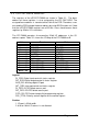
3.3 DO_CSR: DO Control & Status Register
Digital input control and status checking is done by this register.
Address: BASE + 04
Attribute: READ/WRITE
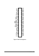
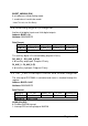
Data Format:
Bit # 3~0 DO_WAIT_NAE DO_MODE DO_32
Bit # 7~4 PG_STOP_TRIG
PB_TERM_OFF DO_WAIT_TRG PAT_GEN
Bit # 11~8 DO_FIFO_FULL
DO_UNDER DO_FIFO_CLR DO_EN
Bit # 15~12 - - BURST_HNDSH (2) DO_FIFO_EMPTY
Bit # 31~16 Don’t Cared
(2) This bit is different between Rev.A and Rev.B.
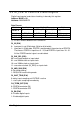
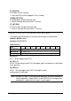
DO_32 (R/W)
0: Output port is not 32-bit wide ( 16-bit or 8-bit wide)
1: Output port is 32-bit wide, PORTA is configured as the extension of PORTB.
That means PORTB is output lines (0…15), and PORTA is output lines
(16…31). All PORTA control signals are disabled.
DO_MODE (R/W)
00: use timer1 output as output clock
01: use 20MHz clock as output clock
10: use 10MHz clock as output clock
11: REQ/ACK handshaking mode