
User`s manual
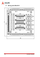
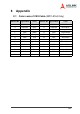

Connection Example 289
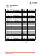
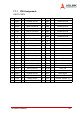
7.6.1 PIN Assignment:
CNIF1-CNIF4
No. Name I/O Function No. Name I/O Function
1 P15R -- 15VDC power supply 2 VLA O Analog speed limit
3 IGND -- Isolated Ground 4 EA+ I Encoder A-phase(+)
5 EA- I Encoder A-phase(-) 6 EB+ I Encoder B-phase(+)
7 EB- I Encoder B-phase(-) 8 EZ+ I Encoder Z-phase(+)
9 EZ- I Encoder Z-phase(-) 10 OUT+ O Pulse Signal(+)
11 OUT- O Pulse Signal(-) 12 N.C
13 N.C 14 N.C
15 SVON O Servo ON 16 SP2 O Speed selection 2
17 ABSM O Forward rotation 18 ABSR O Reverse rotation
19 RES I Reset Signal 20 +24V -- Voltage output
21 +24V -- Voltage output 22 ABSB0 I Speed reached
23 ZSP I Zero Speed 24 INP I In-position Signal
25 TLC I Limiting Torque 26 N.C
27 TC O Analog torque command 28 IGND -- Isolated Ground
29 N.C 30 N.C
31 N.C 32 N.C
33 N.C 34 IGND -- Isolated Ground
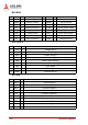
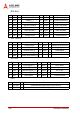
35 DIR+ O Direction Signal(+) 36 DIR- O Direction Signal(-)
37 N.C 38 N.C
39 N.C 40 N.C
41 ERC O Error counter Clear 42 EMG O Emergency stop
43 IGND -- Isolated Ground 44 IGND -- Isolated Ground
45 LOP O Control selection 46 IGND -- Isolated Ground
47 IGND -- Isolated Ground 48 ALM I Servo Alarm Signal
49 RDY I Servo Ready Signal 50 N.C