PCIS-DDE DDE Server for NuDAQ PCI-bus Cards (Win-NT) User’s Guide
@Copyright 1998~1999 ADLink Technology Co., Ltd. All Rights Reserved. Manual Ver. 1.22: November 29, 1999 The information in this document is subject to change without prior notice in order to improve reliability, design and function and does not represent a commitment on the part of the manufacturer.
Getting service from ADLink ♦ Customer Satisfaction is always the most important thing for ADLink Tech Inc. If you need any help or service, please contact us and get it. ADLink Technology Inc. Web Site Sales & Service Technical Support TEL Address ♦ http://www.adlink.com.tw service@adlink.com.tw NuDAQ nudaq@adlink.com.tw NuDAM nudam@adlink.com.tw NuIPC nuipc@adlink.com.tw NuPRO nupro@adlink.com.tw Software sw@adlink.com.tw AMB amb@adlink.com.tw +886-2-82265877 FAX +886-2-82265717 9F, No.
Contents CHAPTER 1 Introduction to PCIS-DDE ................ 1 1.1 W HAT IS DDE......................................................................... 1 1.2 DDE CONVERSATION .............................................................. 3 CHAPTER 2 Getting Started ................................. 5 2.1 PCIS-DDE INSTALLATION ........................................................ 5 2.1.1 2.1.2 2.2 Installation.........................................................................................
4.7 PCI-7434 ............................................................................ 35 4.8 PCI-9111DG/HR.................................................................. 36 4.9 PCI-9112 ............................................................................ 38 4.10 PCI-9113 ............................................................................ 40 4.11 PCI-911 4DG/HG ................................................................. 41 4.12 PCI-9118DG/HG/HR.............................
1 Introduction to PCIS-DDE PCIS-DDE is an application for Windows NT operating systems. It acts as a DDE (Dynamic Data Exchange) Server and allows other Windows application programs to access data from NuDAQ PCI-bus data acquisition cards. It may be used with Wonderware InTouch and any Microsoft Windows program that is capable of acting as a DDE Client. 1.
Client applications can use DDE for one-time data transfers or for continuous data exchanges in which updates are sent as soon as new information is available. For one-time data transfers, the client application only requests the “snapshot” data from the server application. For example, as a macro for report generation is executed in Excel, a link to another DDE program will be set up to request the specified data. The link will be terminated after the requested data is received.
1.2 DDE Conversation Two Windows application wishing to exchange data must establish a conversation. The client opens a channel to the server application by specifying: l Server Application Name For PCIS-DDE server, the application name is PciDDE. l Topic (Logical Device) Name The DDE topic is a general classification of data within which multiple data items may be "discussed" (exchanged) during the conversation. For PCISDDE server, the topic might be a NuDAQ board name with its card number, e.g.
2 Getting Started 2.1 PCIS-DDE Installation 2.1.1 Installation The Setup program in ADLink CD-ROM performs all tasks necessary for complete installation. step 1. Insert the ADLink CD-ROM into your CD-ROM drive. step 2. If Windows NT is loaded, click the Start button on the Taskbar, and then choose Run. Step 3. Type x:\setup (x identifies the drive that contains the compact disc) in Open text box, then click OK. Step 4. Setup first displays the main screen. Select Software Package. Step 5.
install PCIS-DDE in another directory, please click Browse button to change the destination directory. Then you click Next button to go on the installation. When the software component installation process is completed, Setup will launch the driver registry utility, PciUtil, for you to make the driver registries and board configuration. The PciUtil main window is shown as the following window. If any NuDAQ PCI-bus card’s driver has been registered, it will be shown on the Registered Driver list.
From this window, user can select the driver you want to register and type the value in the box corresponding to AI, AO, DI, or DO according to the requirement of your applications. The “Buffer Allocated” of AI, AO, DI, DO represent the sizes of contiguous Initially Allocated memory for continuous analog input, analog output, digital input, digital output respectively. Its unit is KB, i.e. 1024 bytes. Device driver will try to allocate these sizes of memory at system startup time.
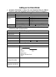
File/Sub-directory PciDDE.exe PciDDE.hlp PciDDE.cnt Wwdlg32.dll Pdde.dll PciDDE.pdf Samples
Samples\NuDAQ.If the device status is none, you have to select the AdlDask, PCI7200, PCI7230, PCI-7234, PCI7250, PCI7248, PCI7296, PCI7432, PCI7433, PCI7434, PCI9111, PCI9112, PCI-9113, PCI-9114, PCI9118, PCI6208 or PCI7252 device and press the “Start” button. Note: The AdlDask driver must have been started as you press Start button to start the card’s own device driver. 2.1.2 PCIS-DDE Device Driver Handling PCIS-DDE provides a utility, PciUtil.
Using this utility to install a new driver, please refer to section 2.1.1. Using PciUtil to change the buffer allocated settings of one of the NuDAQ PCI-bus cards’ device drivers, select the driver from the Registered Driver list and click “Modify…” button and then a “Driver Configuration” window is shown as below. Inside the allocated buffer size fields of AI, AO, DI and DO are the originally set values.
2.2 PCIS-DDE Server Configuration For PCIS-DDE to perform properly, PCIS-DDE server configuration is required before its operation. To perform the required configurations, start up PCIS-DDE by clicking PCIS-DDE V1.2 from program files menu and then the PCIS-DDE Server main window is s hown as follows: The configuration items include Board Configuration, Topic Definition and DDE Server Settings. The detail of the configuration items is described in the following sections. 2.2.
Push this button to close the dialog box. Define a new board and the “NuDAQ Adapter Card Setting” dialog box displays as the figure below. This button appears only as at least one board has been defined. Push this button to modify the settings for the selected board. This button appears only as at least one board is defined. Push this button to delete the selected board.
Reply Timeout:This field is used to input the amount of time (in seconds) the NuDAQ boards on the system will be given to reply to commands from the PCIS-DDE Server. The Timeout message is sent out when a NuDAQ board fails to respond. The value is valid from 1 to 32 and the default value is 3 seconds. 2.2.2 /Configure/Topic Definition To define the Topics, select Topic Definition from Configuration Menu in NuDAQ main window. The topic definition operation is not valid until at least one board is defined.
The following section shows the NuDAQ Topic Definition dialog box and gives the detailed description of each field: Topic Name: This field is used to enter a Topic Name. (The same DDE Topic Name is entered in the InTouch "DDE Access Name definition" dialog box described in the section 3.1). The topic must be a unique name that is matched by the DDE clients (for example InTouch). Topic Name can be up to 32 characters long.
Since each DI/O port of PCI-7248/96 can be set as input port or output port, this button is used to configure the port direction (Input port or output port) of PCI-7248/7296 boards. To perform PCI-7248/96 DI/O port configuration, push this button and the dialog box is shown as the following figure: In this window, you can set each port as an input port or an output port by selecting the port direction from the combo box that is beside each port name.
The fields and buttons in dialog box above are described in the following: Configuration File Directory: This field is used to specify the path (disk drive and directory) in which the PCIS-DDE will save its configuration file. PCIS-DDE will use this path to load the configuration file the next time it is started. Note: Only the "path" may be modified with this field. The configuration file is always named NuDAQ.cfg.
3 Using PCIS-DDE with InTouch 3.1 DDE Item Names Definition in InTouch For InTouch, the DDE item name can be defined in Tag Name Dictionary to read/write data from other applications. To define the tagnames, invoke the /Special/Tag Name Dictionary... command (in WindowMaker).
Enter the Tagname in this field. (The tagname defined here is the name InTouch will use. The PCIS-DDE server does not see this name. The item name that PCIS-DDE server uses is defined in Item Name field, an input field in Details box). Click on this button to select the tag type. The Tag Types dialog box is as follows: To access PCIS-DDE server items, the type of Tagname should be I/O type. There are four I/O types.
After selecting tag types, the "Details" dialog box associated to the tag type will appear: Note: If Details dialog box does not appear, click Details at the top of the Tagname Dictionary dialog box. Input all the information related to the tag name. If selecting I/O Integer or I/O Real as the type for your tagname, it is required to input the values of Min EU, Max EU, Min Raw and Max Raw Click on this button to define the DDE access name associated to the tagname.
Click on this button to close the dialog box. Click on this button to define a new DDE access name. Click on this button to modified the selected DDE access name. An Modify Access Name dialog box will appear. Click on this button to delete the selected DDE access nam e. The following figure illustrate the Add/Modify Access Name dialog box: Enter an arbitrary name. InTouch uses Access Names to reference real-time I/O data of tagname associated to the Access name.
In this field, type the actual program name, PciDDE, for the PCIS-DDE server program from which the data value will be acquired. Note: Do not enter the .exe extension portion of the program name. In this field, type the topic name you want to access. The "Topic Name" MUST be the same name used when the topics were configured in the PCIS I/O DDE Server program.
The last step is to define the DDE item name. In this field, type the item name for the desired data value in the PCIS-DDE server. Please refer to the chapter 4 for the valid item names of each NuDAQ PCI-bus data acquisition cards. For example, to access the digital input value of PCI-7200 module, type PDI in this field. Note: It is important to understand that the "tagname" is the name used within InTouch to refer to a data value.
3.2 Monitor the Communication Status of Modules For each board being used, there is a built-in discrete item, Status, that you can use to monitor the state of the communications with NuDAQ PCI-bus data acquisition cards. Status is set to "0" when communications with the device fails and set to "1" when communications is successful.
3.3 Monitor the Status of an DDE Conversation InTouch also supports a built-in topic name called IOStatus (DDEStatus in versions prior to InTouch 7.0) that can be used to monitor the status of specific DDE conversations. When using the built-in topic IOStatus to monitor an I/O conversation, the item name is the actual Topic Name that you want to monitor.
Excel can also be used to perform this same type of monitoring by entering the same information in a formula in a spreadsheet cell.
4 DDE Item Names In PCIS-DDE The following sections list the commands and the corresponding item names and the data types of NuDAQ PCI-bus data acquisition cards. The Special Command Set is available for all the NuDAQ PCI-bus data acquisition cards. Except special commands, all the item names begin with an “P” character. The definition of each data type is described in section 3.1 of this manual. Please refer to the related section for the details.
4.
* “PASBIn” and “PBIn” (n is the bit number) commands are both used for n-th bit digital data in. For signal bit digital data input, the performance of these two commands are almost the same. However, for multi-bits digital data input, using “PASBIn” can get much higher performance than “PBIn”. Hence “PASBIn” command is especially suitable for multi-bits digital data input. 4.
4.3 PCI-7234 Digital I/O Command Set Command Item Name Digital Data Out in digital format PDO* Digital Data Out in String mode PSDO* Requested/Poked value Data: xxxxxxxxxx Example: 1234567890 Range: -2147483648 ~ 2147483647 Data: xxxxxxxxxx Example: 1234567890 Range: 0 ~ 4294967295 R/W Data Type W Integer W String * For InTouch, the value of N th bit of PDO can be poked/ by using Tag.0N as the item name. For example, to poke the value of the 0 th bit of PDO, set tagname as Tag.
4.
4.
* Since each DI/O port of PCI-7248/96 can be set as input port or output port, the item name PCP is used to configure the direction of each port. One bit of the poked data of PCP controls one port.
* “PASBIn” and “PBIn” (n is the bit number) commands are both used for n-th bit digital data in. For signal bit digital data input, the performance of these two commands are almost the same. However, for multi-bits digital data input, using “PASBIn” can get much higher performance than “PBIn”. Hence “PASBIn” command is especially suitable for multi-bits digital data input. 4.
* To get the value of N th bit of PDI0/PDI1 by using Tag.0N as the item name, the data type of PDI0/PDI1 have to be set as integer. As mentioned before, the “integer” is “32-bit signed integer” in InTouch. That means the range of “integer” is –2147483648 ~ 2147483647. However, to poke or advise the 32-bit unsigned data, use “PRDI0” or “PRDI1” (the data type is real) for digital input. * “PASBIn” and “PBIn” (n is the bit number) commands are both used for n-th bit digital data in.
* To get the value of Nth bit of PDO0/PDO1 by using Tag.0N as the item name, the data type of PDO0/PDO1 have to be set as integer. As mentioned before, the “integer” is “32-bit signed integer” in InTouch. That means the range of “integer” is–2147483648 ~ 2147483647. However, to poke 32-bit unsigned data, use “PSDO0” or “PSDO1” (the data type is string) for digital output. 4.
Analog Input Range Setting PSR Digital Data In from Extended input port PEDI Digital Data Out to Extended output port Nth bit Digital Data In from Extended output channels (N is the bit number) Fast Nth bit Digital Data In from Extended output channels (N is the bit number) PEDO Data Range*: 1 ~ 5 Example: 2, indicates that the AI range is ±5V Data Range: 0~255 Example: 127 Data Range: 0~15 Example: 12 W Integer R Integer W Integer PEBI0…PEBI 15 Data: 0 or 1 R Integer PAEBI0 … PAEBI15* Dat
* “PASAIn” and “PAIn” (n is the channel number) commands are both used for analog data in. For signal channel analog data input, the performance of these two commands are almost the same. However, for multi-channels analog data input, using “PASAIn” can get much higher performance than “PAIn”. Hence “PASAIn” command is especially suitable for multi -channels a nalog data input. * “PASBIn/PAEBIn” and “PBIn/PEBIn” (n is the bit number) commands are both used for n-th bit digital data in.
* In PCIS-DDE, each analog input range is represented by an integer. The valid input ranges and their corresponding integers for PCI-9112 are: Analog Input Range Represented Integer ±10V ±5V ±2.5V ±1.25V ±0.625V 0 ~ 10V 0 ~ 5V 0 ~ 2.5V 0 ~ 1.25V 1 2 3 4 5 15 16 17 18 * “PASAIn” and “PAIn” (n is the channel number) commands are both used for analog data in. For signal channel analog data input, the performance of these two commands are almost the same.
4.
performance than “PAIn”. Hence “PASAIn” command is especially suitable for multi -channels analog data input. 4.
* “PASAIn” and “PAIn” (n is the channel number) commands are both used for analog data in. For signal channel analog data input, the performance of these two commands are almost the same. However, for multi-channels analog data input, using “PASAIn” can get much higher performance than “PAIn”. Hence “PASAIn” command is especially suitable for multi -channels analog data input. * “PASBIn” and “PBIn” (n is the bit number) commands are both used for n-th bit digital data in.
Nth bit Digital Data In (N is the bit PBI0…PBI15 number) Fast Nth bit Digital PASBI0… Data in (N is the bit PASBI3 number) Analog Input Range PSR Setting Data: 0 or 1 R Integer Data: 0 or 1 R Integer For PCI-9118DG/HR Data Range*: 2 ~ 5 (Bipolar) 15 ~ 18 (Unipolar) For PCI-9118HG Data Range*: 2, 7 ~ 9 (Bipolar) 15, 19 ~ 21 (Unipolar) Example: 2, indicates that the AI range is ±5V W Integer * In PCIS-DDE, each analog input range is represented by an integer.
* “PASBIn” and “PBIn” (n is the bit number) commands are both used for n-th bit digital data in. For signal bit digital data input, the performance of these two commands is almost the same. However, for multi-bits digital data input, using “PASBIn” can get much higher performance than “PBIn”. Hence “PASBIn” command is especially suitable for multi-bits digital data input. 4.
4.14 cPCI-7252 Digital I/O Command Set Command Item Name Digital Data In PDI Digital Data Out PDO Nth bit Digital Data In (N is the bit number) PBI0…PBI15 Fast Nth bit Digital PASBI0… Data In (N is the bit PASBI15 number) Requested/Poked R/W Data Type value Data Range: 0 ~ 65535 Example: 128 Data Range: 0 ~ 255 Example: 128 R Integer W Integer Data: 0 or 1 R Integer Data: 0 or 1 R Integer * For InTouch, the value of Nth bit of PDO/PDI can be poked/advised by using Tag.
Appendix InTouch Sample Programs There are several InTouch sample programs provided in this software package. They could help you to program your own applications by using InTouch and PCIS-DDE easily.
9111Demo 9112Demo 9113Demo 9114dgDemo 9118dghgDemo 7252Demo I.
Please refer to chapter 2 for the detailed descriptions about the PCIS-DDE Server configuration. A configuration file “NuDAQ.cfg”, located in Samples directory, is provided. This configuration file defines all the topic names required for executing our sample programs. To use this configuration file, set the configuration file path as the directory where this configuration file is located (the default is “C:\ADLink\Pcisdde\Samples”), and then re-execute PCIS-DDE server program.
II. Converting Raw Data of analog input and analog output to Engineering Unit In InTouch, you can convert raw data of AI and AO to engineering unit in tagname dictionary dialog box. For example, the analog input range is ± 5V and the data range of AI raw data is 0 to 4095 for PCI9112. You can set the range of engineering unit and raw data as the following figure: Since the data conversion will be performed by InTouch, it’s very convenient for users using engineering unit to perform AI/AO in InTouch.