
User`s guide


24 • Registers
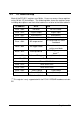
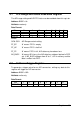
There are 8 bits in this register. Under non-auto scan mode, the 4 LSB
(CN0~CN3) stores the channel number setting with the 4 MSB (AS3~AS0) set
to ‘0’. Under auto-scan mode, the 4LSB records the ending channel number.
The 4 MSB are the selected channel with the value increasing automatically
when an A/D trigger signal is inserted.
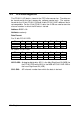
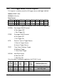
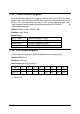
3.6 A/D Input Signal Range Control Register
The A/D range register is used to adjust the analog input range. This register
directly controls the PGA (programmable gain amplifier). When a different
gain value is set, the analog input range will be changed to the its
corresponding value.
Address: BASE + 8h
Attribute: write only
Data Format:
Bit 7 6 5 4 3 2 1 0
BASE+8h X X X X X G2 G1 G0
BASE+9h X X X X X X X X
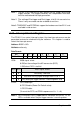
The relationship between gain setting and its corresponding A/D range is listed
in the table below.
G2 G1 G0 GAIN Analog Input Range
Gain Code used in Software
Library
0 0 0 1 ±10V AD_B_10_V
0 0 1 2 ±5V AD_B_5_v
0 1 0 4 ±2.5V AD_B_2_5_V
0 1 1 8 ±1.25V AD_B_1_25_v
1 0 0 16 ±0.625V AD_B_0_625_V