
User`s guide

44 • Operation Theory
The formula between the A/D converted data and the voltage value is:
Voltage AD data
K gain
= × ×_
1 10
Where gain is the value of the A/D gain control register. K=32768 for
PCI-9111HR, and K=2048 for PCI-9111DG.
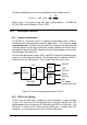
4.2 Interrupt Control
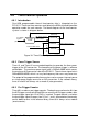
4.2.1 System Architecture
The PCI-9111‘s interrupt system is a powerful and flexible system, which is
suitable for A/D data acquisition and many applications. The system is a Dual
Interrupt System. The dual interrupt means the hardware can generate two
interrupt request signals at the same time and the software can service these
two request signals using ISR. Note that the dual interrupt does not mean the
card occupies two IRQ levels.
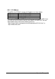
The two interrupt request signals (INT1 and INT2) come from the digital input
signals or the timer/counter output. An interrupt source multiplexer (MUX) is
used to select the IRQ sources. Fig 12 shows the interrupt system.
Figure 13. Dual Interrupt System of the PCI-9111
4.2.2 IRQ Level Setting
There is only one IRQ level is used by this card, although it is a dual interrupt
system. This card uses INT #A interrupt request signal on the PCI bus. The
motherboard circuits will transfer INT #A to one of the AT bus IRQ levels. The
IRQ level is set by the PCI plug and play BIOS and is saved in the PCI
controller. It is not necessary for users to set the IRQ level.
PCI
Controller
INT #A
IRQ
Flip-Flops
INT1
Clear IRQ
INT2
MUX
Pacer
INT2
INT1
MUX
AD EOC
FIFO
Half-full
External
IRQ
Pre
-
trigger
counter reaches 0