NuPRO -595 Series Half Size Socket7 ISA Bus Low Power Pentium SBC With VGA/LCD/Ethernet/WOL Interface User’s Guide
Copyright Notice Manual Rev 1.50: May 24, 2000 This publication is protected by copyright and all rights are reserved. No part of it may be reproduced or transmitted by any means or in any form, without prior consent of the original manufacturer. The information in this document has been carefully checked and is believed to be accurate. However, the original manufacturer assumes no responsibility for any inaccuracies that may appear in this manual.
Getting service from ADLINK ♦ Customer Satisfaction is always the most important thing for ADLINK Tech Inc. If you need any help or service, please contact us and get it. ADLINK Technology Inc. Web Site http://www.adlink.com.tw Sales & Service service@adlink.com.tw NuDAQ nudaq@adlink.com.tw NuDAM nudam@adlink.com.tw Technical NuIPC nuipc@adlink.com.tw Support NuPRO nupro@adlink.com.tw Software sw@adlink.com.tw AMB amb@adlink.com.tw TEL +886-2-82265877 FAX +886-2-82265717 Address 9F, No.
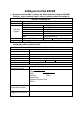
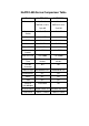
NuPRO-595 Series Comparison Table Model NuPRO-595 NuPRO-596 Processor Intel Pentium Intel Pentium AMD K6-2, K6-3 AMD K6-2, K6-3 Cyrix MII Cyrix MII Processor Socket Socket7 Socket7 Chipset Intel 430TX Intel 430TX BIOS A w ard Award L2 cache 512KB 512KB Max.
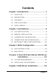
Contents Chapter 1 Introduction . . . . . . . . . . . . . . . . . . . . . . . . 1 1.1 CHECKLIST............................................................1 1.2 DESCRIPTION........................................................2 1.3 FEATURES .............................................................2 1.4 SPECIFICATIONS..................................................3 1.5 INTELLIGENCE......................................................5 Chapter 2 Installations . . . . . . . . . . . . . . .
5.1 INSTALLING THE DRIVERS FOR WINDOWS 95 ...............................................................................66 5.2 INSTALLING THE DRIVERS FOR WINDOWS 98 ...............................................................................66 5.3 INSTALLING THE DRIVERS FOR WINDOWS NT 4.0..........................................................................67 Chapter 6 LAN Driver Installation Guide . 6 8 6.1 INTRODUCTION ..................................................68 6.2 FEATURES ....
1 Introduction This manual is designed to give you information on the NuPRO-595 CPU board. The topics covered in this chapter are as follows: Ø Checklist Ø Description Ø Features Ø Specifications Ø Intelligence Ø Layout of Key Components and Dimensions 1.1 Checklist Please check that your package is complete and contains the items below. If you discover damaged or missing items, please contact your dealer.
• 1 CD Containing Intel PCI IDE Driver, Flash Memory Utility, C&T 69000 VGA Driver, Intel 82559 LAN Driver and Hardware Monitor utility 1.2 Description The NuPRO-595 is a Pentium Industrial CPU board based on the Intel 430TX chipset and is fully designed for harsh industrial environment. It features a Socket7 processor connector that is compatible with Intel Pentium MMX, AMD K6-2, K6-3 and Cyrix MII processors. This board accommodates up to 128MB SDRAM configuration.
1.4 Specifications • Processor Socket: Socket7 connector • Processor: Intel Pentium MMX, Low Power Pentium, AMD K6-2, K6-3 166~400MHz • Bus Speed: 66MHz • Chipset: Intel 82430TX, 82371EB • Secondary Cache: 512KB • Memory Sockets: • One 168-pin DIMM sockets • Max.
• Enhanced IDE: One Enhanced IDE interfaces for up to two devices, support PIO Mode 3/4 or Ultra DMA/33 IDE Hard Disk and ATAPI CD-ROM.,LS120,ZIP • FDD Interface: One floppy drives (360KB, 720KB, 1.2MB, 1.44MB, 2.
• Keyboard and Mouse Connectors: PS/2 type mini-DIN that supports PC/AT; supports a 5-pin external keyboard connector • PICMG Compliance: Fully compliant to PICMG standards • Power supply: AT or ATX • Environmental and Mechanical: • Power Consumption: +5V@11.8A (max), +12V@50mA , -12V @30mA(while K6-3/400 CPU is installed) • Temperature: 0°C to 60°C • Humidity: 5% to 95% • Dimensions: 185mm x 129mm 1.
Figure 1 Layout of key components: 6 • Introduction
Figure 2NuPRO-595 Mechanical Drawing Introduction • 7
2 Installations This chapter provides information on how to use the jumpers and connectors on the NuPRO-595 in order to set up a workable system. The topics covered are: Ø CPU Installation Ø Memory Installation Ø Jumpers on the NuPRO-595 Ø Connectors on the NuPRO-595 Ø Watchdog timer configration 2.1 CPU Installation The NuPRO-595 Industrial CPU Board supports a Socket7 processor socket for Intel Pentium MMX, Low power Pentium, AMD K6-2/-3 and Cyrix MII processors.
Note: Ensure that the CPU heat sink and the CPU top surface are in total contact to avoid CPU overheating problem that would cause your system to hang or be unstable. 2.2 Memory Installation The NuPRO-595 Industrial CPU Board supports a 168-pin DIMM sockets for a maximum total memory of 128 SDRAMs. The memory modules can come in sizes of 16MB, 32MB, 64MB, 128MB SDRAM. 2.
Figure3Jumper Locations on the NuPRO-595 u 10 • Installations
JP7: CPU Core Multiplier The table below shows the correct setting to match the CPU frequency. CPU Type CPU Frequency JP7 2 x 66MHz 133MHz 2.5x 66MHz 166MHz Intel Pentium CPU 3 x 66MHz 200MHz 3.5x 66MHz 233MHz 2(6) x 66MHz 133(400)MHz AMD K6-2(K6-3) 2.5 x 66MHz 166MHz 3.
CPU Type CPU Frequency 3.5 x 66MHz 233MHz 4.0 x 66MHz 266MHz AMD K6-2(K6-3) 4.5 x 66MHz 300MHz 5.0 x 66MHz 333MHz 5.5 x 66MHz 366MHz 2.5 x 66MHz 166MHz Low Power Pentium 4.
CPU Type CPU Frequency JP7 2 x 66MHz 133MHz 2.5x 66MHz 166MHz Cyrix MII 3 x 66MHz 200MHz 3.5x 66MHz 233MHz u JP1 LCD Power Setting 3.
u JP9 : CPU Core voltage VCORE 1.9V 2.0V 2.1V 2.
u VCORE JP9 2.3V 2.4V 2.8V u JP4 , JP5: CPU VI/O JP4 JP5 Voltage 1 3 1 3 1 3 1 3 2.5V 3.
u JP11 , JP12 , JP13: COM2 OUTPUT MODE SETTING COM2 OUTPUT MODE RS-232 RS-422 RS-485 16 • Installations JP11 JP12 JP13
2.4 Connectors on the NuPRO-595 The connectors on the NuPRO-595 allow you to connect external devices such as keyboard, floppy disk drives, hard disk drives, printers, etc. The following tables list the connectors on NuPRO-595 and their respective functions. CONNECTORS ON THE NUPRO-595 ............................. 16 CN4: MISCELLANEOUS CONNECTOR........................... 18 CN1: EXTERNAL KEYBOARD CONNECTOR.................. 20 IDE1: EIDE CONNECTORS.............................................
Figure 4Connector Locations on the NuPRO-595 18 • Installations
u CN4: Miscellaneous Connector The Miscellaneous connector is a 20-pin header that provides interfaces for the following functions. 1 11 Power LED PC Speaker Keylock Reset Switch Hard Disk LED ATX Power Input ATX Power On Switch 10 20 l Speaker: Pins 11 - 14 This connector provides an interface to a speaker for audio tone generation. An 8-ohm speaker is recommended.
l ATX Power ON Switch: Pins19 and 20 This 2-pin connector is an “ATX Power Supply On/Off Switch” on the system that connects to the power switch on the case. When pressed, the power switch will force the system to power on. When pressed again, it will force the system to power off. 19 20 l Reset Switch: Pins 15 and 16 The reset switch allows the user to reset the system without turning the main power switch off and then on again. Orientation is not required when making a connection to this header.
u CN1: External Keyboard Connector 1 u Pin # 1 2 3 4 5 Signal Name Keyboard clock Keyboard data NC GND Vcc IDE1: EIDE Connectors IDE1: Primary IDE Connector Signal Name Pin # Reset IDE 1 Host data 7 3 Host data 6 5 Host data 5 7 Host data 4 9 Host data 3 11 Host data 2 13 Host data 1 15 Host data 0 17 Ground 19 DRQ0 21 Host IOW 23 Host IOR 25 IOCHRDY 27 DACK0 29 IRQ14 31 Address 1 33 Address 0 35 Chip select 0 37 Activity 39 Pin # 2 4 6 8 10 12 14 16 18 20 22 24 26 28 30 32 34 36 38 40 Signal Name G
u CN3: Floppy Drive Connector CN3 is a 34-pin header and will support up to 2.88MB floppy drives.
u CN5: Flat Panel LCD Connector CN5 is a 50-pin (dual in line header) for flat panel LCD displays. The following shows th e pin assignments of this connector. Signal Name VCLK Pin # 1 Pin # 2 Signal Name P33 P34 3 4 P31 P35 5 6 P32 P30 7 8 P28 P29 9 10 P27 P25 11 12 P26 P24 13 14 P21 P23 15 16 P22 P16 17 18 P20 P17 19 20 P18 P19 21 22 P14 P13 23 24 P12 P15 25 26 P11 P7 27 28 PD10 5V 0R 3.3V P9 29 31 30 32 5V 0R 3.
u Flat Panel Display Interface Pin Descriptions Mono Mono Mono DD Color Color Color Color TFT TFT SS DD TFT TFT Pin Name 8-bit 8-bit P0 D0 UD3 16-bit 9/12/16 18/24 36-bit 18/24 bit bit bit UD7 B0 B0 FB0 FB0 P1 D1 UD2 UD6 B1 B1 FB1 P2 D2 UD1 UD5 B2 B2 P3 D3 UD0 UD4 B3 P4 D4 LD3 UD3 P5 D5 LD2 P6 D6 P7 D7 Color Color Color Color Color TFT+HR STN-SS STN-SS STN-DD STN-DD 8-bit (4bP) R1 16-bit (4bP) R1 8-bit (4bP) UR1 16-bit (4bP) UR0 24-bit FB1 B1 G1 UG1
P33 SR3 P34 SR4 P35 SHFCLK Pixels/Clk: u SR5 SHFCLK SHFCLK SHFCLK SHFCLK SHFCLK SHFCLK SHFCLK 8 8 16 1 1 2 2 SHFCLK SHFCLK SHFCLK SHFCLK SHFCLK 2-2/3 5-1/3 2-2/3 5-1/3 8 CN2: Parallel Port Connector The following table describes the pin out assignments of this connector.
u CN11: COM1 Serial Port CN11, a 10-pin header connector, is an onboard serial port of h te NuPRO-590. The following table shows the pin assignments of this connector. Pin # 1 2 3 4 5 6 7 8 9 10 u Signal Name DCD, Data carrier detect RXD, Receive data TXD, Transmit data DTR, Data terminal ready GND, ground DSR, Data set ready RTS, Request to send CTS, Clear to send RI, Ring indicator NC CN10: COM2 Serial Port CN10, a 10-pin header connector, is the onboard COM2 serial port of the NuPRO-595.
u CN9: PS/2 Keyboard Connector Pin # 1 2 3 4 5 6 u Signal Name Keyboard data N.C. GND 5V Keyboard clock N.C. CN8: PS/2 Mouse Connector Pin # 1 2 3 4 5 6 u Signal Name Mouse data N.C. N.C. 5V Mouse Clock N.C. CN6: VGA CRT Connector The pin assignments of the CN6 VGA CRT connector are as follows: Signal Name Red Blue GND GND N.C. N.C. HSYNC NC Pin Pin Signal Name 1 3 5 7 9 11 13 15 2 4 6 8 10 12 14 Green N.C. GND GND GND N.C.
u CN7: RJ45 Connector This connector is for the 10/100Mbps Ethernet capability of the CPU board. The figure below shows the pin out assignments of this connector and its corresponding input jack. TD+(pin#1) T D-(pin#2) RD+(pin#3) RD-(pin#6) u FN1: CPU Fan Power Connector FN1 is a 3-pin header for the CPU fan. The fan must be a 12V fan. 1 u 2 3 Pin # 1 2 Signal Name Rotation +12V 3 Ground CN12: USB Connectors The following table shows the pin outs of the USB connectors.
u LED1: LAN Activity Indicators A and B are Green LED indicators located at the bracket side of the CPU board that shows LAN activity and the transfer rate in progress. Refer to the following table for the functions of each LED status.
2.5 Watchdog Timer Configuration The function of the watchdog timer is to reset the system automatically. It contains a one-second/minute resolution down counter, CRF2 of logical device 8, and two Watchdog control registers, WDT_CTRL0 and WDT_CTRL1 of logical device 8. We can uses compatible PNP protocol to access configuration registers for setting up watchdog timer configuration.
OUT DX,AL MOV MOV OUT MOV MOV OUT DX,3F0H AL,0E2H ;device 7, CRE2 DX,AL DX,3F1H AL,0AH ;Watch Dog Timer Output DX,AL MOV MOV OUT MOV MOV OUT DX,3F0H AL,2AH ;CR2A DX,AL DX,3F1H AL,80H ;bit7=0 -> KBRST, bit7=1 -> GP12 DX,AL MOV MOV OUT MOV MOV OUT DX,3F0H AL,07H DX,AL DX,3F1H AL,08H ;select device 8 DX,AL MOV MOV OUT MOV MOV OUT DX,3F0H AL,0F3H ;device 8, CRF3 DX,AL DX,3F1H AL,06H ;Watch Dog Timer is reset upon a DX,AL ;Mouse & Keyboard interrupt MOV MOV OUT MOV MOV OUT DX,3F0H AL,07H DX,AL DX,3F1H A
MOV MOV OUT MOV MOV OUT DX,3F0H AL,07H DX,AL DX,3F1H AL,08H DX,AL MOV DX,3F0H MOV AL,0F2H ;CRF2 OUT DX,AL MOV DX,3F1H MOV AL,0FH ;Time-out occurs after the value of CRF2 OUT DX,AL ;range 1~255, 00 -> disable Time-out ;----------------------------------;Exit extended function mode ;----------------------------------MOV DX,3F0H MOV AL,0AAH OUT DX,AL EXIT END 32 • Installations
3 BIOS Configuration This chapter describes the different settings available in the Award BIOS. The topics covered in this chapter are as follows: BIOS INTRODUCTION ................................................... 33 BIOS SETUP .................................................................. 33 STANDARD CMOS SETUP............................................. 34 BIOS FEATURES SETUP ............................................... 38 CHIPSET FEATURES SETUP.........................................
3.1 BIOS Introduction The Award BIOS (Basic Input/Output Subroutine) installed in your computer system’s ROM supports Intel Pentium & AMD K6-2/3 processors. The BIOS provides critical low-level support for standard devices such as disk drives, serial ports, and parallel ports. It also adds virus and password protection as well as special support for detailed fine-tuning of the chipset controlling the entire system. 3.
The section below the setup items of the Main Menu displays the control keys for this menu. Another section at the bottom of the Main Menu just below the control keys section displays information on the currently highlighted item in the list. Note: After making and saving system changes with Setup, you find that your computer cannot boot, the Award BIOS supports an override to the CMOS settings that resets your system to its default.
At the bottom of the menu are the control keys for use on this menu. If you need any help in each item field, you can press the key. It will display the relevant information to help you. The memory display at the lower right-hand side of the menu is read-only. It will adjust automatically according to the memory changed. The following describes each item of this menu.
Press / to select a numbered hard disk type or type the number and press the key. The hard disk will not work properly if you enter incorrect information for this field. If your hard disk drive type is not matched or listed, you can use Type User to define your own drive type manually. If you select Type User, related information is asked to be entered to the following items. CYLS.
LCD&CRT The NuPRO-590 CPU board can supports two display interfaces, Panel and CRT, concurrently. This field selects the interface of video display.
u BIOS Features Setup This section allows you to configure and improve your system and allows you to set up some system features according to your preference. ROM / PCI ISA BIOS BIOS FEATURES SETUP AWARD SOFTWARE, INC.
CPU Internal Cache / External Cache Cache memory is additional memory that is much faster than conventional DRAM (system memory). CPUs from 486-type on contain internal cache memory, and most, but not all, modern PCs have additional (external) cache memory. When the CPU requests data, the system transfers the requested data from the main DRAM into cache memory, for even faster access by the CPU. These items allow you to enable (speed up memory access) or disable the cache function.
Swap Floppy Drive This item allows you to determine whether to enable Swap Floppy Drive or not. Enabled The BIOS swaps floppy drive assignments so that Drive A becomes Drive B, and Drive B becomes Drive A. Disabled Disable the BIOS to swap floppy drive Boot Up Floppy Seek Enabled The BIOS will seek whether or not the floppy drive installed has 40 or 80 tracks. 360K type has 40 tracks while 760K, 1.2M and 1.
Typematic Rate Setting Enabled Enable typematic rate and typematic delay programming Disable typematic rate and typematic delay Disabled programming. The system BIOS will use default value of these 2 items And the default controlled by keyboard Typematic Rate (Chars/Sec) When the typematic rate is enabled, the system registers repeated keystrokes speeds. You can select speed range from 6 to 30 characters per second. By default, this item is set to 6.
PCI/VGA Palette Snoop Some non-standard VGA display boards may not show colors properly. This field allows you to set whether MPEG ISA/VESA VGA Boards can work with PCI/VGA or not. Enabled PCI/VGA can work with MPEG ISA/VESA VGA board Disabled PCI/VGA can not work with MPEG ISA/VESA VGA board OS Select for DRAM > 64MB This option allows the system to access greater than 64MB of DRAM memory when used with OS/2 that depends on certain BIOS calls to access memory. The default setting is Non-OS/2.
u Chipset Features Setup This Setup menu controls the configuration of the chipset. ROM PCI/ISA BIOS CHIPSET FEATURES SETUP AWARD SOFTWARE INC.
8 Bit I/O Recovery Time The recovery time is the length of time, which the system delays after the completion of an input/output request. The CPU clocks measure it. This delay takes place because the CPU is operating much faster than the input/output bus that the CPU must be delayed to allow for the completion of the I/O. This option specifies the length of the delay (in sysclks) inserted between consecutive 8-bit I/O operations. The settings are 1, 2, 3, 4, 5, 6, 7, or 8. The default setting is NA.
Spread Spectrum This field sets the value of the spread spectrum. Options are Disabled, 1.8% (CNTR), 0.6% (CNTR), 1.8% (DOWN), and 0.6% (DOWN). The default setting is Disabled. This field is for CE testing use only. Case_Open Warning When the system is power on, to open the system’s case may causes accidental damage. If this field enabled, it alarms by speaker beeping. You must turn off the power and close the system’s case to disable the beeping. The default setting is Disabled.
u Power Management Setup The Power Management Setup allows you to save energy of your system effectively. It will shut down the hard disk and turn off video display after a period of inactivity. ROM PCI/ISA BIOS POWER MANAGEMENT SETUP AWARD SOFTWARE, INC.
PM Control by APM This field allows you to use the Advanced Power Management device to enhance the Max. Power Saving mode and stop the CPU’s internal clock. The default setting of this field is Yes. Video Off Method This field defines the Video Off features. There are three options.
Doze Mode When enabled, and after the set time of system inactivity, the CPU clock will run at a slower speed while all other devices still operate at full speed.
Suspend Mode When enabled, and after the set time of system inactivity, all devices except the CPU will be shut off.
ZZ Active In Suspend The ZZ signal is used to power down a cache’s data SRAMs when the clock logic places the CPU into the stop clock. Enabled Enable the ZZ signal to power down cache’s SRAM Disabled Disable the ZZ signal when in suspend mode PCI/VGA Act-Monitor When enabled, any video activity restarts the global timer for Standby mode. The default setting is Enabled. Soft-Off by PWR-BTTN This field defines the power-off mode when using an ATX power supply.
Reload Global Timer Events This section determines the reloading of the ‘timers’ after entering the Full On You can enable or disable the monitoring of IRQ 8 (Real Time Clock) so it does not awaken the system from Suspend mode. PM Events The VGA, LPT & COM, HDD & FDD, DMA /master, PWR-On by Modem/LAN, RTC Alarm Resume and Primary INTR section are I/O events which can prevent the system from entering a power saving mode or can awaken the system from such a mode.
u PNP/PCI Configuration This option configures the PCI bus system. All PCI bus systems on the system use INT#, thus all installed PCI boards must be set to this value. ROM PCI/ISA BIOS PNP/PCI CONFIGURATION AWARD SOFTWARE INC.
Reset Configuration Data This field allows you to determine whether to reset the configuration data or not. The default value is Disabled. IRQ3/4/5/7/9/10/11/12/14/15, DMA0/1/3/5/6/7 assigned to These fields allow you to determine the IRQ/DMA assigned to the ISA bus and is not available to any PCI slot.
ROM PCI/ISA BIOS CMOS SETUP UTILITY AWARD SOFTWARE, INC.
ROM PCI/ISA BIOS INTEGRATED PERIPHERALSP AWARD SOFTWARE INC.
IDE Primary Master/Slave UDMA These fields allow your system to improve disk I/O throughput to 33Mb/sec with the Ultra DMA/33 feature. The options are Auto and Disabled. On-Chip Primary PCI IDE The integrated peripheral controller contains an IDE interface with support for two IDE channels. Select Enabled to activate each channel separately. USB Keyboard Support Select Enabled if your system contains a Universal Serial Bus (USB) controller and you have a USB keyboard.
Parallel Port Mode This field allows you to determine parallel port mode function. SPP EPP ECP u (Standard Parallel Port) normal Printer Port, 150KB/sec transfer speed (Enhanced Parallel Port), 2MB/sec transfer speed, the system supports EPP 1.7 and EPP 1.9 (Extended Capabilities Port), 4MB/sec transfer speed Supervisor / User Password These two options set the system password. Supervisor Password sets a password that will be used to protect the system and Setup utility.
To disable a password, just press the key when you are prompted to enter the password. A message will confirm the password to be disabled. Once the password is disabled, the system will boot and you can enter Setup freely. ROM PCI/ISA BIOS CMOS SETUP UTILITY AWARD SOFTWARE, INC.
u Save & Exit Setup This option allows you to determine whether to accept the modifications or not. If you type “Y”, you will quit the setup utility and save all changes into the CMOS memory. If you type “N”, you will return to Setup utility. ROM PCI/ISA BIOS CMOS SETUP UTILITY AWARD SOFTWARE, INC.
4 Intel PIIX Bus Master IDE Driver Installation This chapter describes the installation procedure for Intel PCI ISA IDE Xcelerator(PIIX) Bus Master IDE Drivers for Windows 95. This chapter contains the following sections: System Requirements61 INSTALLING THE SOFTWARE ...................................61 4.1 System Requirements This section describes system requirements for the PIIX Bus Master IDE Device Driver for Windows 95 . This driver has been designed for and tested with Windows 95 only.
Windows 95 4.00.950 (Retail) Windows 95 4.00.950a (OSR1) Windows 95 4.00.950b (OSR2 without USB Supplement) Windows 95 4.00.950b (OSR2.1 with USB Supplement) 4. This utility should only be used on desktop systems. The utility must not be executed on notebook or portable systems with or without dock. 5. It is assumed that the BIOS properly initialized the 82371xB IDE interface for Bus Master IDE operation. 6.
5. Click Yes if you agree to continue. NOTE: If you click 'No', the program will terminate. 6. Select INSTALL, to install the PIIX Bus Master IDE Device Driver when prompted to do so. Note: If the driver is currently installed on the system, SETUP will ask you whether or not you want to continue. Follow the prompts on the screen to install the driver if desired. 7. 8. Click 'OK' to restart the system when prompted to do so.
5 VGA Driver Installation This chapter provides information on how to install the C&T 69000 VGA drivers that come in the two floppy diskettes with the package. Please follow the instructions set forth in this chapter carefully. Please note that there must be relevant software installed in your system before you could proceed to install the VGA drivers. It is recommended that you make a copy of the VGA driver diskette and put the backup copy in a safe place.
5.1 Installing the Drivers for Windows 95 The following section describes the normal display driver installation procedures for Windows 95. Use the following procedures when installing the display drivers for Windows 95. 1. 2. 3. 4. 5. 6. 7. 8. 9. Click Start. Select Settings, then click the Control Panel icon. Double click Display. Click Settings. Click Advanced Properties. Click Change. Click Have Disk ....
5.3 Installing the Drivers for Windows NT 4.0 IMPORTANT: You should install the Windows NT 4.0 Service Pack 5 first before installing the C&T 69000 VGA drivers. If you don't have the Windows NT 4.0 Service Pack 5, please contact your software vendor or download it from Microsoft's web site. The procedures below show you how to install the C&T 69000 VGA drivers for Windows NT 4.0. 1. 2. 3. 4. 5. 6. 7. 8. 9. 10. 11. 12. 13. Boot Windows NT 4.0. Double click the My Computer icon.
6 LAN Driver Installation Guide This chapter describes LAN features and driver installation of the onboard Intel 82559 Ethernet controller. The following items are covered in this chapter: INTRODUCTION ...........................................................66 FEATURES ....................................................................67 SOFTWARE DRIVERS SUPPORT ...............................67 RUNNING DIAGNOSTICS ...........................................67 6.
6.2 Features l l l l l l l Conforms to the Ethernet IEEE 802.3u standard Compatible with PCI Local Bus Revision 2.1 specification IEEE 802.3u Auto-Negotiation for automatic speed selection Supports Full-Duplex/Half-Duplex Operation Provides 32-bit bus mastering data transfer Supports 10Mbps and 100Mbps operation in a single port Supports remote wake-up (Magic Packet*) in APM and ACPI mode * Requires ATX power supply with 5VSB, 720mA 6.3 Software Drivers Support NetWare ODI Drivers Novell NetWare 3.x, 4.
1. Run the file SETUP.EXE typing a:\setup or D:\NUPRO\NuPRO595\LAN DRIVER\setup.exe in the DOS prompt, assuming your floppy disk drive is drive A. Upon doing so, the system starts the Setup Utility and shows the following screen. 8255x-based PCI EtherExpress™ adapter Setup V4.
3. Selecting Test adapter will show the following screen. 8255x-based PCI EtherExpress™ adapter Setup V4.21 Test adapter Bus=0 Dev=0Bh Slot=11 Addr=004063001000 IRQ=10 Diagnostic tests: Adapter tests…………………………….. Onboard loopback tests………………… Network test……………………………… 100Mbps Passed Passed Passed This adapter works properly Press Enter to continue Help = F1 4. Press Enter to continue Selecting Install network drivers will show the following screen. 8255x-based PCI EtherExpress™ adapter Setup V4.
5. Upon selecting Others under the Install network drivers main menu screen, the following screen will appear. 8255x-based PCI EtherExpress™ adapter Setup V4.21 Other Other operating systems Choose OTHER if you use a network operating system from a manufacturer not on this list (such as Banyan or UNIX). Help = F1 Previous = Esc 6. Select = ↑↓ Accept = ↵ Selecting View Help files under the Main menu will show the following screen. 8255x-based PCI EtherExpress™ adapter Setup V4.
7 Hardware Doctor Utility This chapter introduces Hardware Doctor Utility that comes with the CPU board in conjunction with the onboard hardware monitoring IC. The sections in the following pages describe the functions of the utility. Hardware Doctor is a self-diagnostic system for PC and must be used with Winbond’s W83781D IC series products. It will protect PC Hardware by monitoring several critical items including Power Supply Voltage, CPU Fan speed, and CPU & System temperature.
Clicking on the upper left corner button would show you the three items as following: 74 • Hardware Doctor Utility
User can set all limits to default value by choosing the “default” item under “file” dialogue window. Set all Limits to Default: If users want to change CPU, please set all limits to default after replacing new CPU and the CPU working voltage Vcore will be load automatically. When Change another CPU, please see Default. Save the Setting Limits Limit Adjustment: All limits by users can be modified and saved. When users execute this program next time, the limit will be the modified value.
Case Open: If your PC case has a sensor for this functions , after marking this item, once the PC case is opened, the warning message will pop up and never disable unless you key in the correct password. Exit: Choosing the “X” button on the right corner of the tool bar in Hardware Doctor main menu, the menu will be minimized on the working bar of Windows 98 and serves as a TSR program. Only choosing the "exit" item under the " file" will exit Hardware Doctor.
Fan Speed: The mos t popular PC system may only have one fan on the motherboard. When the fan is not connected or doesn't exist, the fan speed column will be indicated "Low speed". At this time, please disable the fan in the "configuration" page. CPU fan is located in the m otherboard to keep CPU in normal temperature. If this fan turns low speed or stops, the temperature will be raised and the PC/CPU may be damaged or operate unstably.
Note: Only the fan with three output pins can be monitored! Temperature: All temperature-monitoring items only permit users to change the high limit, and the low limit will be set automatically as the high limit minus 5 degree C. Once the CPU/System temperature over the high limit, the warning message will pop up and status will turn "Red". The status will not recover to be " Green" until the temperature gets lower than the high limit minus 5 degree C.
Product Warranty/Service Seller warrants that equipment furnished will be free from defects in material and workmanship for a period of one year from the confirmed date of purchase of the original buyer and that upon written notice of any such defect, Seller will, at its option, repair or replace the defective item under the terms of this warranty, subject to the provisions and specific exclusions listed herein.