NuDAQ DAQ-2204/2205/2206 PXI-2204/2205/2206 64-CH, High Performance Multi-function Data Acquisition Cards User's Guide
Copyright 2002 ADLINK Technology Inc. All Rights Reserved. Manual Rev. 1.13: Oct 15, 2002 Part No: 50-11213-101 The information in this document is subject to change without prior notice in order to improve reliability, design and function and does not represent a commitment on the part of the manufacturer.
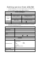
Getting service from ADLINK • Customer Satisfaction is the most important priority for ADLINK Tech Inc. If you need any help or service, please contact us. ADLINK Technology Inc. Web Site http://www.adlinktech.com Sales & Service Service@adlinktech.com NuDAQ + USBDAQ nudaq@adlinktech.com Automation automation@adlinktech.com Technical Support TEL Address • NuIPC nuipc@adlinktech.com NuPRO / EBC nupro@adlinktech.com +886-2-82265877 FAX +886-2-82265717 9F, No.
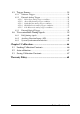
Table of Contents Tables.......................................................................................iv Figures ......................................................................................v How to Use This Guide ..........................................................vii Chapter 1 Introduction ...........................................................1 1.1 1.2 1.3 Features ........................................................................... 1 Applications .....................
Chapter 4 Operation Theory ................................................24 4.1 A/D Conversion............................................................... 24 4.1.1 DAQ/PXI-2204 AI Data Format ................................................ 25 4.1.1.1 Synchronous Digital Inputs (for DAQ/PXI-2204 only) ............. 25 4.1.2 DAQ/PXI-2205/2206 AI Data Format ...................................... 27 4.1.3 Software conversion with polling data transfer acquisition mode (Software Polling) ............
4.5 Trigger Sources ............................................................... 54 4.5.1 4.5.2 Software -Trigger........................................................................... 54 External Analog Trigger .............................................................. 54 4.5.2.1 4.5.2.2 4.5.2.3 4.5.2.4 4.5.2.5 4.5.3 4.6 Below-Low analog trigger condition ........................................ 55 Above-High analog trigger condition .......................................
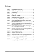
Tables Table 1: Programmable input range...................................... 4 Table 2: Table 3: Table 4: Table 5: Table 6: -3dB small signal bandwidth .................................. 5 System Noise ........................................................ 6 Input impedance .................................................... 6 CMRR (DC to 60Hz) ............................................. 6 Settling time to full-scale step.................................
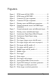
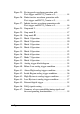
Figures Figure 1: PCB Layout of DAQ-22XX................................. 15 Figure 2: Figure 3: Figure 4: Figure 5: Figure 6: Figure 7: PCB Layout of PXI-22XX................................... 16 Connector CN1 pin assignment............................ 18 Connector CN2 pin assignment............................ 19 Floating source and RSE input connections .......... 22 Ground-referenced sources and NRSE input connections ........................................................
Figure 25: Re-triggered waveform generation with Post-trigger and DLY2_Counter = 0..................... 44 Figure 26: Finite iterative waveform generation with Post-trigger and DLY2_Counter = 0..................... 45 Figure 27: Infinite iterative waveform generation with Post-trigger and DLY2_Counter = 0..................... 46 Figure 28: Figure 29: Figure 30: Figure 31: Figure 32: Stop mode I........................................................ 47 Stop mode II..........................................
How to Use This Guide This manual is designed to help you use/understand the DAQ/PXI-22XX. The manual des cribes the versatile functions and the operation theory of the DAQ/PXI-22XX. It is divided into five chapters: Chapter 1, “Introduction,” gives an overview of the product features, applications, and specifications. Chapter 2, “Installation,” describes how to install DAQ/PXI-22XX. The layout and the positions of all the connectors on DAQ/PXI-22XX are shown.
1 Introduction The DAQ/PXI-22XX is an advanced data acquisition card based on the 32-bit PCI architecture. High performance designs and the state-of-the-art technology make this card ideal for data logging and signal analysis applications in medical, process control, etc. 1.
• Programmable gain P DAQ/PXI-2204: x1, x2, x4, x5, x8, x10, x20, x40, x50, x200. P DAQ/PXI-2205/2206: x1, x2, x4, x8.
1.2 Applications • Automotive Testing • Cable Testing • Transient signal measurement • ATE • Laboratory Automation • Biotech measurement 1.
• Programmable input range: Device Bipolar input range Unipolar input range ±10V -- ±5V 0~10V ±2.5V 0~5V ±2V 0~4V ±1.25V 0~2.5V ±1V 0~2V ±0.5V 0~1V ±0.25V 0~0.5V ±0.2V 0~0.4V ±0.05V 0~0.1V ±10V 0~10V 2205 ±5V 0~5V 2206 ±2.5V 0~2.5V ±1.25V 0~1.
• -3dB small signal bandwidth: (Typical, 25°C) Device 2204 2205 2206 Input range Bandwidth (-3dB) ±10V -- ±5V 0~10V ±2.5V 0~5V ±1.25V 0~2.5V ±2V 0~4V ±0.5V 0~1V ±1V 0~2V ±0.25V 0~0.5V ±0.2V 0~0.4V ±0.05V 0~0.1V ±10V 0~10V 1600kHz ±5V 0~5V 1400kHz ±2.5V 0~2.5V 1000kHz ±1.25V 0~1.25V 600kHz ±10V 0~10V 760kHz ±5V 0~5V 720kHz ±2.5V 0~2.5V 610kHz ±1.25V 0~1.
• System Noise (LSBrms, including Quantization, Typical, 25°C) Device Input Range System Noise Input Range System Noise ±10V 0.95 LSBrms 0~10V 1.5 LSBrms ±5V 1.0 LSBrms 0~5V 1.6 LSBrms ±2.5V 1.1 LSBrms 0~2.5V 1.7 LSBrms ±1.25V 1.3 LSBrms 0~1.25V 1.9 LSBrms ±10V 0.8 LSBrms 0~10V 0.9 LSBrms ±5V 0.85 LSBrms 0~5V 1.0 LSBrms ±2.5V 0.85 LSBrms 0~2.5V 1.0 LSBrms ±1.25V 0.9 LSBrms 0~1.25V 1.
• Settling time to full-scale step: (Typical, 25°C) Device Input Range Condition Settling time ±10V ±5V 0~10V ±2.5V Multiple channels, 0~5V multiple ranges. ±2V 0~4V All samples in Unipolar OR Bipolar mode ±1.25V 0~2.5V ±0.5V 1us to 0.1% error 0~1V ±10V ±5V 0~10V ±2.5V 2204 Multiple channels, 0~5V multiple ranges. ±2V 0~4V All samples in Unipolar AND/OR Bipolar mode ±1.25V 0~2.5V ±0.5V 0~1V 0~2V Multiple channels, multiple ranges. ±1V All samples in Unipolar ±0.25V 0~0.
• Time-base source: Internal 40MHz or External clock Input (fmax: 40MHz, fmin: 1MHz, 50% duty cycle) • Trigger modes: post-trigger, delay-trigger, pre-trigger and middle-trigger • Offset error: P Before calibration: ±60mV max P After calibration: ±1mV max • Gain error: P Before calibration: ±0.6% of output max P After calibration: ±0.03% of output max for DAQ/PXI-2204 ±0.
• Output range: ±10V, 0~10V, ±AOEXTREF, 0~AOEXTREF • Settling time: 3µS to 0.5LSB accuracy • Slew rate: 20V/uS • Output coupling: DC • Protection: Short-circuit to ground • Output impedance: 0.1Ω. max. • Output driving: ±5mA max. • Stability: Any passive load, up to 1500pF • Power-on state: 0V steady-state • Power-on glitch: ±1V/500uS • Offset error: P Before calibration: ±80mV max P After calibration: ±1mV max • Gain error: P Before calibration: ±0.
• Synchronous Digital Inputs (SDI): For DAQ/PXI-2204 only • Number of channels: 4 digital inputs sampled simultaneously with the analog signal input. • Compatibility: TTL/CMOS • Input voltage: P Logic Low: VIL=0.8 V max.; IIL=0.2mA max. P High: VIH=2.0V max.; IIH=0.
♦ Digital Trigger (D.Trig) • Compatibility: TTL/CMOS • Response: Rising or falling edge • Pulse Width: 10ns min ♦ System Synchronous Interface (SSI) • Trigger lines: 7 ♦ Stability • Recommended warm-up time: 15 minutes • On-board calibration reference: P Level: 5.000V P Temperature coefficient: ±2ppm/°C P Long-term stability: 6ppm/1000Hr ♦ Physical • Dimension: P 175mm by 107mm for DAQ-22XX P Standard CompactPCI form factor for PXI-22XX • I/O connector: 68-pin female VHDCI type (e.g.
1.4 Software Support ADLINK provides versatile software drivers and packages for users’ different approach to building up a system. ADLINK not only provides programming libraries such as DLL for most Windows based systems, but also ® provide drivers for other software packages such as LabVIEW . All software options are included in the ADLINK CD. Non-free software drivers are protected with licensing codes.
1.4.3 PCIS-OCX: ActiveX Controls We suggest customers who are familiar with ActiveX controls and VB/VC++ programming use PCIS-OCX ActiveX control component libraries for developing applications. PCIS-OCX is designed for Windows 98/NT/2000. For more detailed information about PCIS-OCX, please refer to the user's guide in the CD. (\Manual_PDF\Software\PCIS-OCX\PCIS-OCX.PDF) The above software drivers are shipped with the card.
2 Installation This chapter describes how to install the DAQ/PXI-22XX. The contents of the package and unpacking information that you should be aware of are outlined first. The DAQ/PXI-22XX performs an automatic configuration of the IRQ, and port a ddress. Users can use software utility, PCI_SCAN to read the system configuration. 2.
2.2 Unpacking Your DAQ/PXI-22XX SERIES card contains electro-static sensitive components that can be easily be damaged by static electricity. Therefore, the card should be handled on a grounded anti-static mat. The operator should be wearing an anti-static wristband, grounded at the same point as the anti-static mat. Inspect the card module carton for obvious damages. Shipping and handling may cause damage to your module.
Figure 2: 2.4 PCB Layout of PXI-22XX PCI Configuration 1. Plug and Play: As a plug and play component, the card requests an interrupt number via its PCI controller. The system BIOS responds with an interrupt assignment based on the card information and on known system parameters. These system parameters are determined by the installed drivers and the hardware load seen by the system. 2. Configuration: The board configuration is done on a board-by-board basis for all PCI boards on your system.
3 Signal Connections This chapter describes the connectors of the DAQ/PXI-22XX, and the signal connection between the DAQ/PXI-22XX and external devices. 3.1 Connectors Pin Assignment DAQ/PXI-22XX is equipped with two 68-pin VHDCI-type connectors (AMP-787254-1). It is used for digital input / output, analog input / output, and timer/counter signaling, etc.
AI0 (AIH0) AI1 (AIH1) AI2 (AIH2) AI3 (AIH3) AI4 (AIH4) AI5 (AIH5) AI6 (AIH6) AI7 (AIH7) AI8 (AIH8) AI9 (AIH9) AI10 (AIH10) AI11 (AIH11) AI12 (AIH12) AI13 (AIH13) AI14 (AIH14) AI15 (AIH15) AISENSE AI16 (AIH16) AI17 (AIH17) AI18 (AIH18) AI19 (AIH19) AI20 (AIH20) AI21 (AIH21) AI22 (AIH22) AI23 (AIH23) AI24 (AIH24) AI25 (AIH25) AI26 (AIH26) AI27 (AIH27) AI28 (AIH28) AI29 (AIH29) AI30 (AIH30) AI31 (AIH31) EXTATRIG Figure 3: 1 2 3 4 5 6 7 8 9 10 11 12 13 14 15 16 17 18 19 20 21 22 23 24 25 26 27 28 29 30 31 32
DA0OUT DA1OUT AOEXTREF NC DGND EXTWFTRIG EXTDTRIG SSHOUT RESERVED RESERVED AFI1 AFI0 GPTC0_SRC GPTC0_GATE GPTC0_UPDOWN GPTC0_OUT GPTC1_SRC GPTC1_GATE GPTC1_UPDOWN GPTC1_OUT EXTTIMEBASE PB7 PB5 PB3 PB1 PC7 PC5 DGND PC3 PC1 PA7 PA5 PA3 PA1 Figure 4: 1 2 3 4 5 6 7 8 9 10 11 12 13 14 15 16 17 18 19 20 21 22 23 24 25 26 27 28 29 30 31 32 33 34 35 36 37 38 39 40 41 42 43 44 45 46 47 48 49 50 51 52 53 54 55 56 57 58 59 60 61 62 63 64 65 66 67 68 AOGND AOGND AOGND NC DGND DGND DGND SDI0 / DGND* SDI1 / DGND* SDI
Legend: Signal Name Reference Direction AIGND -------- -------- AI<0..63> AIGND Input AISENSE AIGND Input EXTATRIG DA0OUT DA1OUT AOEXTREF AOGND EXTWFTRIG EXTDTRIG AIGND AOGND AOGND AOGND -------DGND DGND Input Output Output Input -------Input Input RESERVED -------- Output SDI<0..
3.2 Analog Input Signal Connection The DAQ/PXI-22XX provides up to 64 single-ended or 32 differential analog input channels. You can fill the Channel Gain Queue to get desired combination of the input signal types. The analog signal can be converted to digital value by the A/D converter. To avoid ground loops and obtain a more accurate measurement from the A/D conversion, it is quite important to understand the signal source type and how to choose the analog input modes: RSE, NRSE, and DIFF mode. 3.2.
Referenced Single-ended (RSE) Mode In referenced single-ended mode, all the input signals are connected to the ground provided by the DAQ/PXI-22XX. It is suitable for connections with floating signal sources. Figure 5 shows an illustration. Note that when more than two floating sources are connected, these sources will be referenced to the same common ground. CN1 Input Multipexer Instrumentation AIn Amplifier Floating Signal Source V1 + V2 + To A/D - Converter AIGND n = 0, ...
resistor at each channel to provide a bias return path. The resistor value should be about 100 times the equivalent source impedance. If the source impedance is less than 100ohms, you can simply connect the negative side of the signal to AIGND as well as the negative input of the Instrumentation Amplifier without any resistors. In differential input mode, less noise couples into the signal connections than in single-ended mode. Ground Referenced Signal Source x = 0, ...
4 Operation Theory The operation theory of the functions on the DAQ/PXI-22XX is described in this chapter. The functions include the A/D conversion, D/A conversion, Digital I/O and General Purpose Counter / Timer. The operation theory can help you understand how to configure and program the DAQ/PXI-22XX. 4.1 A/D Conversion When using an A/D converter, users should firs t know about the properties of the signal to be measured.
4.1.1 DAQ/PXI-2204 AI Data Format 4.1.1.1 Synchronous Digital Inputs (for DAQ/PXI-2204 only) When each AD conversion is completed, the 12-bit converted digital data accompanied with 4 bits of SDI<3..0> from CN2 will be latched into the 16-bit register and data FIFO, as shown in Fig 9 and Fig 10. Therefore, users can simultaneously sample one analog signal with four digital signals. The data format of every acquired 16-bit data is of the form: D11, D10, D9 .......
Table 8 and 9 illustrate the ideal transfer characteristics of some input ranges. Description Bipolar Analog Input Range Full-scale Range ±10V ±5V ±2.5V Digital code ±1.25V Least significant bit 4.88mV 2.44mV 1.22mV 0.61mV FSR-1LSB 9.9951V 4.9976V 2.4988V 1.2494V 7FFX Midscale +1LSB 4.88mV 2.44mV 1.22mV 0.61mV 001X Midscale Midscale –1LSB 0V 0V 0V 0V 000X -4.88mV -2.44mV -1.22mV -0.61mV -FSR -10V -5V -2.5V -1.
4.1.2 DAQ/PXI-2205/2206 AI Data Format The data format of the acquired 16-bit A/D data is 2’s Complement coding. Table 10 and 11 shows the valid input ranges and the ideal transfer characteristics. Description Full-scale Range Bipolar Analog Input Range ±10V Least significant 305.2uV bit FSR-1LSB 0V Midscale -1LSB -305.2uV -FSR ±5V ±2.5V ±1.25V 152.6uV 76.3uV 38.15uV 9.999695V 4.999847V 2.499924V 1.249962V Midscale +1LSB 305.2uV Midscale Digital code -10V 7FFF 152.6uV 76.3uV 38.
4.1.3 Software conversion with polling data transfer acquisition mode (Software Polling) This is the easiest way to acquire a single A/D data. The A/D converter starts one conversion whenever the dedicated software command is executed. Then the software would poll the conversion status and read the A/D data back when it is available. This method is very suitable for applications that needs to process A/D data in real time.
4.1.4 Programmable scan acquisition mode 4.1.4.1 Scan Timing and Procedure It's recommended that this mode be used if your applications need a fixed and precise A/D sampling rate. You can accurately program the period between conversions of individual channels.
2. The SI_counter is a 24-bit counter and the SI2_counter is a 16-bit counter. Therefore, the maximum scan interval using the internal Timebase = 2 24/40M s = 0.419s, and the maximum sampling interval between 2 channels using the internal Timebase = 216/40M s = 1.638ms. 3. The scan interval can’t be smaller than the product of the data sampling interval and the NumChan_counter value. The relationship can be represented as: SI_counter>=SI2_counter * NumChan_counter.
Scan with SSH You can send the SSHOUT signal on CN2 to an external S&H circuits to sample and hold all signals if you want to simultaneously sample all channels in a scan, as illustrated in fig 11. Note: The ‘SSHOUT’ signal is sent to external S&H circuits to hold the analog signal. Users must implement external S&H circuits on their own to carry out the S&H function. There are no on-board S&H circuits. 4.1.4.
4.1.4.3 Trigger Modes DAQ/PXI-22XX provides 3 trigger sources (internal software, external analog and digital trigger sources). You must select one of them as the source of the trigger event. A trigger event occurs when the specified condition is detected on the selected trigger source (For example, a rising edge on the external digital trigger input).
Note that if a trigger event occurs when a scan is in progress, the data acquisition won’t stop until the scan completes, and the stored M scans of data includes the last scan.
(M_Counter = M = 3 , NumChan_Counter=4, PSC_Counter=0) Trigger Scan_start AD_conversion Scan_in_progress (SSHOUT)(pin8 on CN2) Acquisition_in_progress Acquired & stored data (2 scans) Operation start Figure 14: Pre-trigger with M_enable = 0 (trigger occurs before M scans) (M_counter = M = 3, NumChan_counter=4, PSC_counter=0) The first M scans Trigger signals which occur in the shadow region(the first M scans) will be ignored Trigger Scan_start AD_conversion Scan_in_progress (SSHOUT)(pin2 on CN2) Acquisit
Middle-Trigger Acquisition Use middle-trigger acquisition in applications where you want to collect data before and after a trigger event. The number of scans (M) stored before the trigger is specified by M_counter, while the number of scans (N) after the trigger is specified by PSC_counter. Like pre-trigger mode, the number of stored data could be fewer than the specified amount of data (NumChan_counter *(M+N)) if an external trigger occurs before M scans of data are converted.
(M_Counter=M=2, NumChan_Counter=4, PSC_Counter=N=2) Trigger occurs when a scan is in progress Trigger Scan_start AD_conversion Scan_in_progress (SSHOUT )(pin8 on CN2) Acquisition_in_progress Acquired data M scans before trigger Operation start N scans after trigger Acquired & stored data (M+N scans) Figure 17: Middle trigger (trigger occurs when a scan is in progress) Post-Trigger Acquisition Use post-trigger acquisition in applications where you want to collect data after a trigger event.
Delay Trigger Acquisition Use delay trigger acquisition in applications where you want to delay the data collecting process after the occurrence of a specified trigger event. The delay time is controlled by the value, which is pre-loaded in the Delay_counter (16bit). The counter counts down on the rising edge of the Delay_counter clock source after the trigger condition is met.
data. The process repeats until the specified amount of re-trigger signals are detected. The total acquired data length = NumChan_counter * PSC_counter * Retrig_no. (NumChan _Counter=4, PSC_Counter=2, retrig_no=3) Trigger Scan_start AD_conversion Scan_in_progress (SSHOUT )(pin8 on CN2) Acquisition_in_progress Acquired & stored data (6 scans) Operation start Figure 20: Post trigger with retrigger 4.1.4.
of conversion into their specified counters. After the AD trigger condition is matched, the data will be transferred to the system memory by the bus -mastering DMA. The PCI controller also supports the function of scatter/gather bus mastering DMA, which helps the users to transfer large amounts of data by linking all the memory blocks into a continuous linked list.
4.2 D/A Conversion There are 2 channels of 12-bit D/A output available in the DAQ/PXI-22XX. When using D/A converters, users should assign and control the D/A converter reference sources for the D/A operation mode and D/A channels. Users could also select the output polarity: unipolar or bipolar. The reference selection control lets users fully utilize the multiplying characteristics of the D/A converters. Internal 10V reference and external reference inputs are available in the DAQ/PXI-22XX.
The D/A conversion is initiated by a trigger source. Users must decide how to trigger the D/A conversion. The data output will start when a trigger condition is met. Before the start of D/A conversion, D/A data is transferred from PC’s main memory to a buffering Data FIFO. There are two modes of the D/A conversion: Software Update and Timed Waveform Generation are described, including timing, trigger source control, trigger modes and data transfer methods.
4 update counts, 3 iterations (UC _Counter=4, IC_Counter=3) Trigger UC_Counter=4 DAWR WFG_in_progress Delay until DLY1_Counter reaches 0 Delay until DLY2_Counter reaches 0 Delay until DLY2_Counter reaches 0 DA update_interval t= UI_Counter/Timebase 4 2 Output Waveform 0 -4 Operation start A single waveform IC_Counter = 3 Figure 22: Typical D/A timing of waveform generation (Assuming the data in the data buffer are 2V, 4V, -4V, 0V) Note: The maximum D/A update rate is 1MHz.
4.2.2.1 Trigger Modes Post-Trigger Generation Use post trigger when you want to perform DA waveform right after a trigger event occurs. In this trigger mode DLY1_Counter is not used and you don’t need to specify it. Figure 23 shows a single waveform generated right after a trigger signal is detected. The trigger signal could come from a software command, an analog trigger or a digital trigger. Please refer to section 4.5 for detailed information.
8 update counts, 1 iteration (UC _Counter=8, IC_Counter=1) Trigger DAWR WFG_in_progress Output Waveform Delay until DLY1_counter reaches 0 Operation start Figure 24: Delay trigger waveform generation (Assuming the data in the data buffer are 2V, 4V, 6V, 3V, 0V, -4V, -2V, 4V) Post-Trigger or Delay-Trigger with Re-trigger Use post-trigger or delay-trigger with re-trigger function when you want to generate waveform after more than one trigger events.
4.2.2.2 Iterative Waveform Generation Set IC_Counter in order to generate iterative waveforms from the data of a single waveform. The counter stores the iteration number, and the iterations could be finite (Figure 26) or infinite(Figure 27). Note that in infinite mode the waveform generation won’t stop until software stop function is executed, and IC_Counter is still meaningful when stop mode III is selected. Please refer to 4.2.2.3 for details.
4 update counts, infinite iterations (UC _Counter=4, IC_Counter=3) Trigger waveform generation won’t stop until software stop function is executed DAWR WFG_in_progress Output Waveform 2 4 0 Operation start Figure 27: Infinite iterative waveform generation with Post-trigger and DLY2_Counter = 0 (Assuming the data in the data buffer are 2V, 4V, 2V, 0V) Delay2 in iterative Waveform Generation To stretch out the flexibility of the D/A waveform generation, we add a DLY2 Counter to separate 2 consecutive w
In stop mode III, after a software stop command is given, the waveform generation won’t stop until the performed number of waveforms is a multiple of IC_Counter. See figure 30 for an example, since IC_Counter is set to 3, the total generated waveforms must be a multiple of 3 (waveforms = 6 in this example), and the total DA update counts must be a multiple of 12 (UC_Counter * IC_Counter). You can compare these three figures for their differences.
4 update counts, infinite iterations (UC _Counter=4, IC_Counter=3) Trigger DAWR WFG_in_progress Output Waveform 2 4 0 Operation start Software stop command Figure 30: Stop mode III 4.3 Digital I/O DAQ/PXI-22XX contains 24-lines of general-purpose digital I/O (GPIO), which is provided through a 82C55A chip. The 24-lines GPIO are separated into three ports: Port A, Port B and Port C.
4.4 General Purpose Timer/Counter Operation Two independent 16-bit up/down timer/counter are designed within FPGA for various applications.
4.4.2.1 Mode1: Simple Gated-Event Counting In this mode, the counter counts the number of pulses on the GPTC_CLK after the software-start. Initial count can be loaded from software. Current count value can be read-back by software any time without affecting the counting. GPTC_GATE is used to enable/disable counting. When GPTC_GATE is inactive, the counter halts the current count value. Figure 31 illustrates the operation with initial count = 5, count-down mode.
4.4.2.3 Mode 3: Single Pulse-width Measurement In this mode the counter counts the pulse-width of the signal on GPTC_GATE in terms of GPTC_CLK. Initial count can be loaded from software. After the software-start, the counter counts the number of active edges on GPTC_CLK when GPTC_GATE is in its active state. After the completion of the pulse-width interval on GPTC_GATE, GPTC_OUT outputs high and then current count value can be read-back by software.
4.4.2.5 Mode5: Single Triggered Pulse Generation This function generates a single pulse with programmable delay and programmable pulse-width following an active GPTC_GATE edge. You could specify these programmable parameters in terms of periods of the GPTC_CLK input. Once the first GPTC_GATE edge triggers the single pulse, GPTC_GATE takes no effect until the software-start is re-executed. Figure 35 illustrates the generation of a single pulse with a pulse delay of two and a pulse-width of four.
4.4.2.7 Mode7: Single Triggered Continuous Pulse Generation This mode is similar to mode5 except that the counter generates continuous periodic pulses with programmable pulse interval and pulse-width following the first active edge of GPTC_GATE. Once the first GPTC_GATE edge triggers the counter, GPTC_GATE takes no effect until the software-start is re-executed. Figure 37 illustrates the generation of two pulses with a pulse delay of four and a pulse-width of three.
4.5 Trigger Sources We provide flexible trigger selections in the DAQ/PXI-22XXseries products. In addition to the internal software trigger, DAQ/PXI-22XX also supports external analog, digital triggers and SSI triggers. Users can configure the trigger source by software for A/D and D/A processes individually. Note that the A/D and the D/A conversion share the same analog trigger. 4.5.1 Software-Trigger This trigger mode does not need any external trigger source.
Trigger Level digital setting Trigger voltage 0xFF 9.92V 0xFE 9.84V --- --- 0x81 0.08V 0x80 0 0x7F -0.08V --- --- 0x01 -9.92V Table 14: Analog trigger SRC1 (EXTATRIG) ideal transfer characteristic The trigger signal is generated when the analog trigger condition is satisfied. There are five analog trigger conditions in DAQ/PXI-22XX. DAQ/PXI-22XX uses 2 threshold voltages: Low_Threshold and High_ Threshold to build the 5 different trigger conditions.
4.5.2.2 Above-High analog trigger condition Figure 41 shows the above-high analog trigger condition, the trigger signal is generated when the input analog signal is higher than the High_Threshold voltage, and the Low_Threshold setting is not used in this trigger condition. Figure 41: Above-High analog trigger condition 4.5.2.
4.5.2.4 High-Hysteresis analog trigger condition Figure 43 shows the high-hysteresis analog trigger condition, the trigger signal is generated when the input analog signal level is greater than the High_Threshold voltage, and the Low_Threshold voltage determines the hysteresis duration. Figure 43: High-Hysteresis analog trigger condition 4.5.2.
4.5.3 External Digital Trigger An external digital trigger occurs when a rising edge or a falling edge is detected on the digital signal connected to the EXTDTRIG or the EXTWFTRG of the 68-pin connector for external digital trigger. The EXTDTRIG is dedicated for A/D process, and the EXTWFTRG is used for D/A process. Users can program the trigger polarity through ADLINK’s software drivers easily.
4.6 User-controllable Timing Signals In order to meet the requirements for user-specific timing and the requirements for synchronizing multiple cards, the DAQ/PXI-22XX series provides flexible user-controllable timing signals to connect to external circuitry or additional cards. The whole DAQ timing of the DAQ/PXI-22XX series is composed of a bunch of counters and trigger signals in the FPGA. These timing signals are related to the A/D, D/A conversions and Timer/Counter applications.
4.6.1 DAQ timing signals The user-controllable DAQ timing-signals contains: (Please refer to 4.1.4.1 for the internal timing signal definition) 1. TIMEBASE, providing TIMEBASE for all DAQ operations, which could be from internal 40MHz oscillator, EXTTIMEBASE from I/O connector or the SSI_TIMEBASE. Note that the frequency range of the EXTTIMEBASE is 1MHz to 40MHz, and the EXTTIMEBASE should be TTL-compatible. 2.
Summary of the auxiliary function input signals and the corresponding functionalities Category Timing signal Functionality Constraints 1. TTL-compatible EXTTIMEBASE Dedicated input Replace the internal TIMEBASE 2. 1MHz to 40MHz 3. Affects on both A/D and D/A operations EXTDTRIG 1. TTL-compatible External digital 2. Minimum pulse width = trigger input for 20ns A/D operation 3. Rising edge or falling edge EXTWFTRG 1. TTL-compatible External digital 2.
EXTDTRIG and EXTWFTRIG EXTDTRIG and EXTWFTRIG are dedicated digital trigger input signals for A/D and D/A operations respectively. Please refer to section 4.5.3 for detailed descriptions. EXTTIMEBASE When the applications needs specific sampling frequency or update rate that the card could not generate from its internal TIMEBASE, the 40MHz clock, users could utilize the EXTTIMEBASE with internal counters to achieve the specific timing intervals for both A/D and D/A operations.
AFI[1] Regarding the D/A operations, users could directly input the external D/A update signal to replace the internal DAWR signal. This is another way to achieve customized D/A update rates. The external DAWR signal can only be inputted from the AFI[1]. Note that the AFI[1] is a multi-purpose input, and it can only be utilized for one function at any one time. AFI[1] currently only has one function. ADLINK reserves it for future development. 4.6.
In PCI form factor, there is a connector on the top right corner of the card for the SSI. Refer to section 2.3 for the connector position. All the SSI signals are routed to the 20-pin connector from the FPGA. To synchronize multiple cards, users can connect a special ribbon cable (ACL-SSI) to all the cards in a daisy-chain configuration In PXI form factor, we utilize the PXI trigger bus built on the PXI backplane to provide the necessary timing signal connections.
When the digital trigger condition of Card 1 occurs, Card 1 will internally generate the ADCONV signal and output this ADCONV signal to SSI_ADCONV signal of Card 2, 3 and 4 through the SSI/PXI connectors. Thus we can achieve 16-channel acquisition simultaneously. You could arbitrarily choose each of the 6 timing signals as the SSI master from any one of the cards. The SSI master can output the internal timing signals to the SSI slaves. With the SSI, users could achieve better card-to-card synchronization.
5 Calibration This chapter introduces the calibration process to minimize AD measurement errors and DA output errors. 5.1 Loading Calibration Constants The DAQ/PXI-22XX is factory calibrated before shipment by writing the associated calibration constants of TrimDACs to the on-board EEPROM. TrimDACs are devices containing multiple DACs within a single package. TrimDACs do not have memory capability. That means the calibration constants do not retain their values after the system power is turned off.
5.2 Auto-calibration By using the auto-calibration feature of the DAQ/PXI-22XX, the calibration software can measure and correct almost all the calibration errors without any external signal connections, reference voltages, or measurement devices. The DAQ/PXI-22XX has an on-board calibration reference to ensure the accuracy of auto-calibration. The reference voltage is measured at the factory and adjusted through a digital potentiometer by using an ultra-precision calibrator.
Warranty Policy Thank you for choosing ADLINK. To understand your rights and enjoy all the after-sales services we offer, please read the fo llowing carefully. 1. Before using ADLINK’s products, please read the user manual and follow the instructions exactly. When sending in damaged products for repair, please attach an RMA application form. 2. All ADLINK products come with a two-year guarantee, free of repair charge. 3. 4.
5. To ensure the speed and quality of product repair, please download an RMA application form from our company website www.adlinktech.com . Damaged products with RMA forms attached receive priority. For further questions, please contact our FAE staff. ADLINK: service@adlinktech.com Test & Measurement Product Segment: NuDAQ@adlinktech.com Automation Product Segment: Automation@adlinktech.com Computer & Communication Product Segment: NuPRO@adlinktech.com ; NuIPC@adlinktech.