N u P R O-780 BIOS U s e r ’s G u i d e
@Copyright 2001 ADLINK Technology Inc. All Rights Reserved. Manual Rev. 1.00: November 12, 2001 The information in this document is subject to change without prior notice in order to improve reliability, design and function and does not represent a commitment on the part of the manufacturer.
Table of Contents 1. BIOS SETUP INTRODUCTION ........................................ 1 2. STANDARD CMOS FEATURES........................................ 2 3. ADVANCED BIOS FEATURES .......................................... 6 4. ADVANCED CHIPSET FEATURES................................. 10 5. INTEGRATED PERIPHERALS........................................ 13 6. POWER MANAGEMENT SETUP.................................... 17 7. PNP/PCI CONFIGURATION............................................ 20 8.
1. BIOS Setup Introduction The Award BIOS provides a Setup utility program for specifying the system configurations and settings. The BIOS ROM of the system stores the Setup utility. When you turn on the computer, the Award BIOS is immediately activated. Pressing the key immediately allows you to enter the Setup utility. If you are a little bit late pressing the key, POST (Power On Self Test) will continue with its test routines, thus preventing you from invoking the Setup.
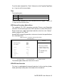
2. Standard CMOS Features "Standard CMOS Setup" item allows you to record some basic hardware configurations in your computer system and set the system clock and error handling. If the motherboard is already installed in a working system, you will not need to select this option. You will need to run the Standard CMOS option, however, if you change your system hardware configurations, the onboard battery fails, or the configuration stored in the CMOS memory was lost or damaged.
To set the date, highlight the “Date” field and use the PageUp/ PageDown or +/- keys to set the current date. Time The time format is: Hour Minute Second 00 to 23 00 to 59 00 to 59 To set the time, highlight the "Time" field and use the / or +/- keys to set the current time. IDE Primary/Secondary Master/Slave The onboard PCI IDE connectors provide Primary and Secondary channels for connecting up to four IDE hard disks or other IDE devices.
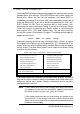
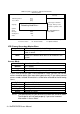
CMOS Setup Utility – Copyright (C) 1984-2001 Award Software IDE Primary Master IDE HDD Auto-Detection [Press Enter] IDE Primary Master [Auto] Access Mode [Auto] Item Help Menu Level Selects the type of fixed disk. *Capacity 6480 MB Detecting Hard Drive… *Cylinder 12556 *Head 16 *Precomp 65535 *Landing Zone 12556 *Sector ‘User type’ will let you select the number of cylinders, heads, etc.
The Capacity item automatically adjust according to the configuration. Drive A / Drive B These fields identify the types of floppy disk drive A or drive B that hasbeen installed in the computer. The available specifications are: None 360KB 5.25 in. 1.2MB 5.25 in. 720KB 3.5 in. 1.44MB 3.5 in. 2.88MB 3.5 in. No floppy drive be installed 5.25 inch floppy drive, 360KB capacity 5.25 in. floppy drive, 1.2MB capacity 3.5 in. floppy drive, 720KB capacity 3.5 in. floppy drive, 1.44MB capacity 3.5 in.
3. Advanced BIOS Features This section allows you to configure and improve your system and allows you to set up some system features according to your preference.
internal cache memory, and most, but not all, modern PCs have additional (external) cache memory. When the CPU requests data, the system transfers the requested data from the main DRAM into cache memory, for even faster access by the CPU. These items allow you to enable (speed up memory access) or disable the cache function.
Boot Up Floppy Seek Enabled The BIOS will seek whether or not the floppy drive installed has 40 or 80 tracks. 360K type has 40 tracks while 760K, 1.2M and 1.44M all have 80 tracks Disabled BIOS will not search the type of floppy disk drive by track number Boot Up NumLock Status On Keypad is number keys Off Keypad is arrow keys Gate A20 Option This field allows you to select how Gate A20 is worked. Gate A20 is a device used to address memory above 1 MB.
Setup the system always boots up and prompts for the Supervisor Password only when the Setup utility is called up System the system prompts for the User Password every time you boot up NOTE: To disable security, select PASSWORD SETTING at Main Menu and then you will be asked to enter the password. If you do not type anything and just press key, it will disable security. Once the security is disabled, you can boot up the system and access to Setup freely.
4. Advanced Chipset Features This Setup menu controls the configuration of the chipset.
NOTE: All related settings of SDRAM are set to Auto. It means that all parameters of SDRAM are decided by the SPD value of Memory. BIOS will use the optimized settings to configure the SDRAM that on your system. System BIOS Cacheable When this function is enabled, the BIOS ROM’s addresses at F0000H-FFFFFH will be duplicated into the SRAM. It will work with the cache controller that is enabled.
an aperture of maximum size. The choices are 32MB and 64MB. Display Cache Frequency You can use this item to select the frequency of the display cache. The choices are 100MHz and 133MHz. FWH Write Protection To protect the BIOS from destroying by some reasons, this item lets user to select the protection type to avoid BIOS errors. Disabled User can flash BIOS anywhere. TBL_Only Top Block Lock, top block area doesn’t change when flashing the new BIOS. Enabled User can’t flash the newer BIOS file.
5. Integrated Peripherals This option sets your hard disk configuration, mode and port.
differ in timing. When Auto is selected, the BIOS will select the best available mode. Auto Mode0~Mode4 Auto select which mode that BIOS communicates with the controller and CPU User define the PIO mode IDE Primary/Secondary Master/Slave UDMA These fields allow your system to improve disk I/O throughput to 33Mb/sec with the Ultra DMA/33 feature. Intel 815E chipset supports up to ATA100 feature. The options are Auto and Disabled.
Onboard Lan Boot ROM This item allows you to decide to support PXE function or not. The PXE function can lets system boot from a network environment. To support it, it also need a DHCP server to link the system. We only support this function from the onboard 82562EM Lan chip.The default setting is Disabled. Onboard FDC Controller Select Enabled if your system has a floppy disk controller (FDC) installed on the system and you wish to use it.
message will be displayed on the screen: ”EPP Mode Select”. At this time either EPP 1.7 spec. or EPP 1.9 spec. can be chosen.
6. Power Management Setup The Power Management Setup allows you to save energy of your system effectively. It will shut down the hard disk and turn off video display after a period of inactivity.
Video Off Method This field defines the Video Off features. There are three options. V/H SYNC + Blank This selection will cause the system to turn off the Vertical and horizontal synchronization ports and Write blanks to the video buffer DPMS Allows the BIOS to control the video display card if it supports the DPMS feature Blank Screen This option only writes blanks to the video buffer Video Off In Suspend This determines the manner in which the monitor is blanked. The default is Yes.
Soft-Off by PWR-BTTN This field defines the power-off mode when using an ATX power supply. There are two modes: Instant-Off The mode allows powering off immediately upon pressing the power button Delay 4 Sec The system powers o ff when the power button is pressed for more than four seconds or places the system in a very low-power-usage state, with only enough circuitry receiving power to detect power button activity.
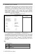
7. PNP/PCI Configuration This option configures the PCI bus system. All PCI bus systems on the system use INT#, thus all installed PCI cards must be set to this value. CMOS Setup Utility – Copyright (C) 1984-2001 Award Software PnP/PCI Configurations Reset Configuration Data [Enabled] Resources Controlled By [Auto(ESCD)] IRQ Resources Press Enter DMA Resources Press Enter PCI/VGA Palette Snoop [Disabled] Item Help Menu Level Default is Disabled.
PCI/VGA Palette Snoop Some non-standard VGA display cards may not show colors properly. This field allows you to set whether MPEG ISA/VESA VGA cards can work with PCI/VGA or not.
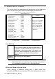
8. PC Health Status CMOS Setup Utility – Copyright (C) 1984-2001 Award Software PC Health Status CPU Warning Temperature [Disabled] Item Help Current System Temp. Current CPU Temperature Menu Level Current System2 Temperature Current CPU FAN Speed Select the limit of CPU VCORE temperature. When CPU + 2.5V Temperature exceeds the + 3.3V limit.
9. Frequency/Voltage Control CMOS Setup Utility – Copyright (C) 1984-2001 Award Software Frequency/Voltage Control Auto Detect DIMM/PCI Clk Enabled CPU Clock/Spread Spectrum Default Item Help Menu Level á â à ß : Move Enter : Select +/-/PU/PD : Value F10 : Save ESC : Exit F1 : General Help F5 : Previous Values F6 : Fail-Safe Defaults F7 : Optimized Defaults Auto Detect DIMM/PCI Clk This item allows you to enable/disable auto detect DIMM/PCI Clock. The default is Disabled.
10. Load Fail-Safe Defaults This option allows you to load the troubleshooting default values permanently stored in the BIOS ROM. These default settings are non-optimal and disable all high-performance features.
12. Set Supervisor / User Password These two options set the system password. Supervisor Pas sword sets a password that will be used to protect the system and Setup utility. User Password sets a password that will be used exclusively on the system. To specify a password, highlight the type you want and press . The Enter Password: message prompts on the screen. Type the password, up to eight characters in length, and press . The system confirms your password by asking you to type it again.
13. Save & Exit Setup Save & Exit Setup This option allows you to determine whether to accept the modifications or not. Typing Y will quit the setup utility and save all changes into the CMOS memory. Typing N will return to Setup utility.