PXI-7921 24-CH, Multiplexer DPDT Relay Module User’s Manual Recycled Paper
© Copyright 2004 ADLINK Technology Inc. All Rights Reserved. Manual Rev. 1.00: July 9, 2004 Part Number: 50-17011-100 The information in this document is subject to change without prior notice in order to improve reliability, design, and function and does not represent a commitment on the part of the manufacturer.
Getting Service from ADLINK Customer Satisfaction is top priority for ADLINK Technology Inc. If you need any help or service, please contact us. ADLINK TECHNOLOGY INC. Web Site http://www.adlinktech.com Sales & Service TEL Address Service@adlinktech.com +886-2-82265877 FAX +886-2-82265717 9F, No. 166, Jian Yi Road, Chungho City, Taipei, 235 Taiwan Please email or FAX your detailed information for prompt, satisfactory, and consistent service.
Table of Contents Chapter 1 Introduction............................................................... 1 1.1 Features............................................................................... 1 1.2 Applications ........................................................................ 2 1.3 Specifications...................................................................... 2 1.4 Software Support ................................................................ 3 Chapter 2 Installation...................
How to Use This Manual This User Manual is designed to assist users in the installation of the ADLINK PXI-7921, 24-CH Multiplexer DPDT Relay PXI Switch module. Chapter 1 Introduction Gives an outline and overview of ADLINK switch modules’ features, specifications, and applications. Chapter 2 Installation Describes how to install a switch module into a PXI chassis. For software library and utilities installation, please refer to the Software Users’ Guide.
1 Introduction ADLINK PXI-7921 is a relay multiplexer module which consists of 24 2-wire relays (DPDT, 2 Form C). PXI-7921 provides 48x1 1-wire and 24x1 2-wire and 12x1 4-wire configurations and typically connects one instrument, such as a DMM, a digitizer or a signal source, with many points which need measurement or excitation. Relays of PXI-7921 can be updated by either direct-update mode or auto-scan mode. The latter mode supports scanlist of 1k-sample for deterministic scanning.
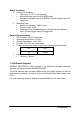
1.2 Applications • • • • • • • Industrial ON/OFF control External high power relay driving and signal switching Laboratory automation Industrial automation Switch contact status sensing Limit switch monitoring Cooperating with other modules such as A/D and D/A peripherals to implement a data acquisition and control system 1.3 Specifications Relay Output • • • • • • • • Number of channels: 24 Relay type: DPDT (2 Form C), non-latching Switching capacity: • Max. switching current: 2A • Max.
Safety functions • • Emergency shutdown • Logic level: 3.
2 Installation This chapter describes the installation process for the ADLINK switch module. Please read the contents of the package and the disassembling information carefully as they are important in the implementation of the ADLINK switch module. 2.
Note: DO NOT APPLY POWER TO THE MODULE IF IT HAS BEEN DAMAGED. You are now ready to install the PXI-7921. 2.3 Mechanical Drawing Figure 1: ADLINK Switch Module ADLINK switch module is packaged in a Eurocard form factor compliant with PXI Specifications measuring 160 mm in length and 100 mm in height (not including connectors). A 62-pin connector is located at the front panel for wiring purposes and the J1/J2 IEC connectors in the rear are used to link the chassis backplane.
insert the switch module into the chassis. Once inserted, a “click” can be heard from the ejector latch. Tighten the screws on the front panel.
3 Signal Connection 3.1 PXI-7921 Topology The ADLINK PXI-7921 is the armature relay multiplexer module which consists of a 24×1 2-wire multiplexer. It also can operate as two groups of 12x1 2-wire multiplexer, four groups of 6×1 2-wire multiplexer, one group of 48×1 1-wire multiplexer, or one group of 12×1 4-wire multiplexer. These configurations are totally software programmable.
3.2 PXI-7921 Pin Assignments & Descriptions 43. 44. 45. 46. 47. 48. 49. 50. 51. COM2+ COM2COM3+ COM3CH18+ CH18CH19+ CH19CH20+ 10 • Signal Connection 22. 23. 24. 25. 26. 27. 28. 29. 30. 31. +5 VOUT CH8+ CH8CH9+ CH9CH10+ CH10CH11+ CH11CH12+ 1. 2. 3. 4. 5. 6. 7. 8. 9.
52. 53. 54. 55. 56. 57. 58. 59. 60. 61. 62. CH20CH21+ CH21CH22+ CH22CH23+ CH231WireloRef* TRG_IN S_ADV SHDNn 32. 33. 34. 35. 36. 37. 38. 39. 40. 41. 42. CH12CH13+ CH13CH14+ CH14CH15+ CH15CH16+ CH16CH17+ CH17- 10. 11. 12. 13. 14. 15. 16. 17. 18. 19. 20. 21. CH4CH5+ CH5COM0+ COM0COM1+ COM1CH6+ CH6CH7+ CH7GND *not used in two-wire mode Table 1: Pin Assignment (2 wire) 43. 44. 45. 46. 47. 48. 49. 50. 51. 52. 53. 54. 55. 56. 57. 58. 59. 60. 61. 62. 22. 23. 24. 25. 26. 27. 28. 29. 30. 31. 32. 33. 34. 35.
46. 47. 48. 49. 50. 51. 52. 53. 54. 55. 56. 57. 58. 59. 60. 61. 62. COM3CH6B+ CH6BCH7B+ CH7BCH8B+ CH8BCH9B+ CH9BCH10B+ CH10BCH11B+ CH11B1WireloRef* TRG_IN S_ADV SHDNn 26. 27. 28. 29. 30. 31. 32. 33. 34. 35. 36. 37. 38. 39. 40. 41. 42. CH9ACH10A+ CH10ACH11A+ CH11ACH0B+ CH0BCH1B+ CH1BCH2B+ CH2BCH3B+ CH3BCH4B+ CH4BCH5B+ CH5B- 4. CH1A5. CH2A+ 6. CH2A7. CH3A+ 8. CH3A9. CH4A+ 10. CH4A11. CH5A+ 12. CH5A13. COM0+ 14. COM015. COM1+ 16. COM117. CH6A+ 18. CH6A19. CH7A+ 20. CH7A21.
COM0± (one wire) COM<0..3>± (two wire) COM<0..1>A±(four wire) COM<0..1>B± (four wire) CH<0..47> (one wire) CH<0..23>± (two wire) CH<0..11>A± (four wire) CH<0..11>B± (four wire) Input/Output Common---The common for each bank. Input/Output Channels---Where signals are connected to the switch card. CHχ+ and CHχ- are switched together. Table 4: Pin Description 3.3 TB-6221 Terminal Board Users can use the TB-6221 terminal board that consists of a printed circuit with screw terminals.
2-wire MUX This configuration has one 24x1 2-wire multiplexer Bank0, which has twentyfour channels. The following diagram illustrates the terminal board pin definition.
2-wire, 2-group MUX This configuration has two 12x1 2-wire multiplexers Bank0 and Bank1, each has twelve channels. The following diagram illustrates the terminal board pin definition.
2-wire, 4-group MUX This configuration has four 6x1 2-wire multiplexers Bank0, Bank1, Bank2 and Bank3, each has six channels. The following diagram illustrates the terminal board pin definition.
1-wire MUX This configuration has one 48x1 1-wire multiplexer Bank0, which has fortyeight channels. The following diagram illustrates the terminal board pin definition.
4-wire MUX This configuration has one 12x1 4-wire multiplexer Bank0, which has twelve channels. The following diagram illustrates the terminal board pin definition.
4 Operation Theorem 4.1 Hardware Block Diagram The ADLINK PXI Switch Module features an onboard FPGA for relay switching control, trigger control, scanlist storage and sequencing. The PXI triggering and synchronization functions, such as Star Trigger and Trigger Bus are also supported.
4.2 Operation Mode The ADLINK PXI Switch Module provides two relay operation modes to accommodate different application requirements. Direct-update The Switch Module updates the relay pattern immediately upon receiving a software command. This mode provides a straightforward control over switch module with minimal hardware intervention. If relay contact bouncing is of a concern, users would need to insert software delay. ADLINK recommends the debounce time to be at least 5ms on PXI-7921.
connectors, and signals in the dotted-line box represents switch module’s internal signal. Figure 8: Available signal sources for Trigger In Software Trigger TRG_IN Trigger Bus [7…0] Trigger In Signal AUX[2…0] Star Trigger In Scanner Advanced After updating the relay pattern, the switch module starts its debounce timer and waits for the relay contacts to settle.
Figures 10 and 11 depict the relationship between Trigger In, Scanner Advanced, and relay pattern in handshaking mode. In Figure 11 the Scanner Advanced is set to pulsating mode.
TS is the default debounce time for a switch module, i.e. 5ms for PXI-7921. TAn is the user specified scan delay time in the scanlist entry, indicating the time between the relay being debounced and the exact moment that a measurement device takes a new measurement. The actual delay time would be the greater of the two times, to guarantee that measurement devices take measurements after the signal path is fully settled, and the relays switch as close as possible to their maximum operating speed.
module. ADLINK PXI Switch module Scanner Advanced Output (S_ADV) External Trigger Input (Trig In) Trigger Input (TRG_IN) Wiring Agilent 33401A 6-1/2 DMM Measurement Complete (VM Comp) Figure 12: Signal Connection between Switch Module and Agilent DMM For more information on scanlist configuration, scan mode setup, start, and stop functions of the auto-scanning process, please refer to the software programming users’ guide. 4.
Software Trigger Trigger In Signal Scanner Adv. Signal AUX [3…2] Trigger Bus[7..0] Star Trigger In WDT Overflow SHDNn Figure 13: Available signal sources for Trigger Bus[7..0] 4.5 Star Trigger The PXI specification defined 13 matched trigger lines to connect to the first 13 PXI peripheral slots on a PXI backplane. Users can route various trigger signal to synchronize multiple PXI instruments and achieve tight timing control.
Software Trigger Trigger In Signal Scanner Adv. Signal Trigger Bus [7…0] Star Trigger Out AUX [2…0] WDT Overflow SHDNn Figure 10: Available signal sources for Star Trigger 4.6 Auxiliary Digital I/O The eight auxiliary digital I/O lines on ADLINK Switch Modules provide versatility to users’ control applications. Each digital I/O line can be input, output or tri-stated. When in output mode, users can still read back the actual logiclevel on the I/O line.
4.7 Hot-Swap The Switch Module can be hot-swapped during hardware failure in noninterruptible or high-availability systems where system shutdown is not an option. PXI-7921 incorporates an onboard hot-swap control mechanism. However the extent of the hot-swap functionality support depends on the operating system and the PXI platform. ® Microsoft Embedded XP supports the native hot-swap function.
AUX2/SHDNn Trigger Bus Shutdown Trigger Star Trigger In Figure 12: Available trigger sources for emergency shutdown The default relay pattern for emergency shutdown is All-Off on PXI-7921; users can change the pattern by Windows API. Upon receiving the emergency shutdown trigger, the Switch Module enters shutdown mode, and the relay pattern is switched to the preset state.
Int. WDTimer Trigger Bus WDT Overflow Star Trigger In Figure 13:.Available trigger sources for watchdog timer overflow The watchdog timer overflow interval can be programmed through Windows API. After enabling the watchdog timer, users must periodically reset the timer by software command. If the timer is not being reset within the specified interval, the switch module will generate an overflow signal and set the relay pattern to the one specified by users. This function is disabled by default.
Warranty Policy Thank you for choosing ADLINK. To understand your rights and enjoy all the after-sales services we offer, please read the following carefully: 1. Before using ADLINK’s products please read the user manual and follow the instructions exactly. 2. When sending in damaged products for repair, please attach an RMA application form. 3. All ADLINK products come with a two-year guarantee, repaired free of charge. • The warranty period starts from the product’s shipment date from ADLINK’s factory.