
User`s manual


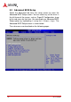
Table Of Contents
- NuPRO-935A
- Revision History
- Preface
- Table of Contents
- List of Figures
- List of Tables
- 1 Introduction
- 2 Hardware Information
- 2.1 Rear Panel I/O Ports
- 2.2 Board Layout
- 2.3 Onboard Connectors
- ATX 12V Power Connector (CN7)
- CPU Fan Connector (FAN2)
- System Fan Connector (FAN1)
- IDE Connector (CN10)
- Floppy disk drive connector (CN8)
- Parallel Port (CN13)
- HD Audio Daughter Board Connector (CN4)
- COM1 Connector (RS-422/485/485+) (CN6)
- COM1/COM2 Connector (RS-232) (CN5/6)
- USB 2.0 Connector (CN11-12)
- External Keyboard/Mouse Connector (CN19)
- Serial ATA Connectors (CN2-3)
- System Panel Connector (CN1)
- 2.4 Jumpers
- 3 Getting Started
- 4 Driver Installation
- 5 BIOS Setup
- Appendix A - Watchdog Timer
- Appendix B System Resources
- Important Safety Instructions
- Getting Service

BIOS Setup 45
NuPRO-935A
5.2 Main Setup
When you first enter the Setup Utility, you will enter the Main setup
screen. You can always return to the Main setup screen by select-
ing the Main tab. There are two Main Setup options. They are
described in this section. The Main BIOS Setup screen is shown
below.
System Time/System Date
Use this option to change the system time and date. Highlight Sys-
tem Time or System Date using the < Arrow > keys. Enter new val-
ues using the keyboard. Press the < Tab > key or the < Arrow >
keys to move between fields. The date must be entered in MM/
DD/YY format. The time is entered in HH:MM:SS format.
Note: The time is in 24-hour format. For example, 5:30 A.M. appears as
05:30:00, and 5:30 P.M. as 17:30:00.