PXIS-2680P 8-Slot 3U PXI Portable Instrument Chassis with 300W+300W AC Power Supply User’s Manual Manual Rev. 2.00 Revision Date: January 28, 2005 Part No: 50-17019-100 Advance Technologies; Automate the World.
Copyright 2005 ADLINK TECHNOLOGY INC. All Rights Reserved. The information in this document is subject to change without prior notice in order to improve reliability, design, and function and does not represent a commitment on the part of the manufacturer. In no event will the manufacturer be liable for direct, indirect, special, incidental, or consequential damages arising out of the use or inability to use the product or documentation, even if advised of the possibility of such damages.
Getting Service from ADLINK Customer Satisfaction is top priority for ADLINK Technology Inc. Please contact us should you require any service or assistance. ADLINK TECHNOLOGY INC. Web Site: http://www.adlinktech.com Sales & Service: Service@adlinktech.com TEL: +886-2-82265877 FAX: +886-2-82265717 Address: 9F, No. 166, Jian Yi Road, Chungho City, Taipei, 235 Taiwan Please email or FAX this completed service form for prompt and satisfactory service.
Table of Contents Table of Contents..................................................................... i List of Tables.......................................................................... iii List of Figures ........................................................................ iv 1 Introduction ........................................................................ 1 1.1 1.2 1.3 Features............................................................................... 2 Specifications.............
3.2 3.3 Trigger Bus ................................................................... 24 System Reference Clock .............................................. 25 Mechanical Drawing........................................................... 26 Pin Assignment .................................................................. 27 System Controller ......................................................... 27 Star Trigger ...................................................................
List of Tables Table Table Table Table Table Table Table 1-1: 3-1: 3-2: 3-3: 3-4: 3-5: 3-6: Electrical Output ....................................................... 3 JP2 and JP3 PXI Reference Clock Control ............ 25 System Slot (Slot #1) P1 Pin Assignment .............. 27 System Slot (Slot #1) P2 Pin Assignment .............. 28 Star Trigger Slot (Slot #2) P1 Pin Assignment ....... 29 Star Trigger Slot (Slot #2) P2 Pin Assignment .......
List of Figures Figure 1-1: PXIS-2680P 3U PXI Portable Instrument Chassis .... 1 Figure 1-2: PXIS-2680P Mechanical Drawing.............................. 5 Figure 1-3: PXIS-2680P Front Panel View................................... 6 Figure 1-4: PXIS-2680P Rear View ............................................. 6 Figure 1-5: PXIS-2680P Left Hand Side View ............................. 7 Figure 1-6: PXIS-2680P Right Hand Side View ........................... 7 Figure 2-1: System Controller Installation .......
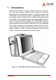
1 Introduction ADLINK PXIS-2680P is a highly integrated and fully mobile 3U PXI instrument chassis offering 8-slot capacity for modules. Defined as the next generation solution for rugged portables, the PXIS-2680P has many high impact, surpassingly flexible, and exceedingly powerful characteristics. It features one dedicated slot for a system controller and seven general purpose slots for peripheral PXI and CompactPCI modules.
The PXIS-2680P includes a 15” SVGA LCD touch screen—an additional monitor is not necessary. No additional LCD, touch panel, or keyboard wiring is required when using either the ADLINK PXD-3710/3710F or the PXI-3800 system controller as all necessary wiring has been integrated through the PXIS-2680P. A built-in DVD combo drive is suitable for high speed recording or backup of valuable data.
1.2 Specifications Complies with PXI Rev.2.2 specifications and accepts modules compliant with CompactPCI, PICMG 2.0 specifications Electrical X AC Power Supply Z Dual 300W mini redundant, hot-swappable power supply, current sharing for all voltage Z Input voltage: 115 to 230VAC, auto selectable Z Input frequency: 47 to 63Hz ± 5% Z Output: AC +3.3V +5V -5V +12V -12V +5Vsb Max. Load 24A 0.8A 2.0A Min. Load 0.3A 3.0A 0.1A 2.0A 0.1A 30A 0.5A 15A 0.
Cooling X Two 8cm, 12VDC ball bearing fans, 41CFM air flow/each Physical X Number of PXI/CompactPCI slots: 8 (1 controller, 7 peripherals) X Number of controller expansion slots: 3 (total 4-slot) X Dimensions: 400mm x 291mm x 230mm (W x H x D, without fan frame) X Net weight: 12kg without system controller and modules Operating Environment X Ambient temperature: 0 to 50°C X Relative humidity: 20 to 90% @ 40°C, noncondensing Storage Environment Temperature X Ambient temperature: -20 to 60°C X
Reliability X MTBF: Z Backplane: 800,000hrs Z Power Supply: 100,000hrs @ full load 1.
Outline Figure 1-3: PXIS-2680P Front Panel View Figure 1-4: PXIS-2680P Rear View 6 Introduction
Figure 1-5: PXIS-2680P Left Hand Side View Figure 1-6: PXIS-2680P Right Hand Side View Introduction 7
8 Introduction
2 Getting Started In this chapter, the unpacking procedure of the sub-system and how to configure a portable PXI system is described. 2.1 Unpacking Checklist Check the shipping carton for any damage. If the shipping carton or its contents are damaged, please do not hesitate to notify the dealer for a replacement. Retain this shipping carton and packing material for inspection by the dealer. Check for the following items in the package. If any items are missing, contact your dealer.
Figure 2-1: System Controller Installation 2. Push the handle until it clips in place. You will hear a click sound when the handle has been pulled up.
3. Insert the controller board mounting screws and screw tightly. Figure 2-3: Mount the Controller Card with Screws 4. When taking out the controller card, unscrew the mounting screws and push the controller out.
Peripheral Module Installation 1. Smoothly slide the peripheral module into an available peripheral slot. Make sure that the peripheral module is aimed toward the rails. Never force the peripheral module into the slot. 2. Push the handle until it clips in place. You will hear a click sound when the handle has been pulled up. 3. Insert the mounting screws and screw tightly. 4. When taking out the peripheral module, unscrew the mounting screws and push the switch out.
Removing and Installing a Power Supply 1. Unscrew and remove the side panel.
2. Pull out the power supply while pressing. Figure 2-7: Removing the Power Supply (B) 3. To replace, push and slide in the new.
2.3 Operation Instructions How to Release Keyboard and Touch Pad There are two release buttons located at the top-left and top-right on the backside of the keyboard. After pressing in these two buttons, you can disengage the keyboard from PXIS-2680P. Two mounting feet located beneath the keyboard and are inserted on the portable for stability. The keyboard can now be lifted upward and freely removed for usage.
How to Setup the Keyboard The keyboard cable is located on the top portion of the keyboard; it is a coil cable with an RJ-45 connector at the end. The connector needs to be attached to the portable (at the lower right hand corner) for operation.
Keyboard Positioning The keyboard angle can be adjusted by tilting the keyboard feet located at the bottom. Figure 2-11: Positioning the Keyboard Touchpad Operation The touch pad operates similar to a mouse and is used to move the cursor in the graphic user interface (GUI) environment by placing and moving your finger. Two buttons located below the touch pad act as same as the left and right buttons of a mouse. You can also tap on the touch pad to indicate a left click.
LCD Display The LCD display has a fixed mechanism. You can pull up the pair of feet at the bottom of the case to lift the LCD display upwards. To relock the LCD display, simply enclose the keyboard and push the feet back into its original position. Before using touch panel functionality, you have to install the touch panel driver according to your operating system. Please refer to section 2.4 for details.
Figure 2-14: PXIS-2680P DVD-ROM Cooling Fans The cooling fans are located at the rear of the chassis for easy access. There are two cooling fans running at a total of 79CFM to ensure that the whole unit be within its working temperature. They can be easily exchanged a newer or better one.
2.4 Software Installation To enable the touch panel functionality, users need to first install the driver into the system controller. To install the driver, please insert the ADLINK T&M All-in-One CD shipped with PXIS-2680P into the DVD-ROM. Drivers for different operating systems can be found at: X:\Driver Installation\PXI Platform\PXI chassis\PXIS2680P\Touch_Panel\Driver Where X:\ is the DVD-ROM. After installing the proper driver, the touch panel function can be used. 2.
The LCD On/Off button turns the LCD on or off with each press. Power LED Temp.
22 Getting Started
3 Backplane Overview The cBX-3008L backplane can accept both PXI compatible products and standard CompactPCI products. The signals on the P1 connector of the backplane meet CompactPCI specifications for both peripheral and system modules. PXI-specific signals are located on P2.
Figure 3-1: PXI Local Bus and Star Trigger Routing Local Bus The PXI backplane local bus of the cBX-3008L is a daisy-chained bus that connects each peripheral slot with its adjacent peripheral slots at the left and right. Each local bus is 13 lines wide and can pass analog or digital signals between modules or provide a highspeed side-band communication path that does not affect the PXI bus bandwidth.
asynchronous external events the system is monitoring or controlling. System Reference Clock The PXIS-2680P supplies the PXI 10MHz system clock signal (PXI_CLK10) independently to every peripheral slot. An independent buffer (having a source impedance matched to the backplane and a skew of less than 1ns between slots) drives the clock signal to each peripheral slot.
3.2 Mechanical Drawing The following figures show the two parts of the backplanes and mechanical drawing.
3.3 Pin Assignment System Controller Pin Z A B C D 25 24 E F GND +5V REQ64# ENUM# GND AD[1] +5V V(I/O) +3.3V +5V GND AD[0] ACK64# GND 23 GND +3.3V AD[4] 22 GND AD[7] GND AD[3] +5V AD[2] GND +3.3V AD[6] AD[5] GND 21 GND +3.3V AD[9] AD[8] GND 20 GND AD[12] GND V(I/O) AD[11] 19 GND +3.3V AD[15] AD[14] GND 18 GND SERR# GND +3.3V PAR 17 GND +3.3V 16 GND DEVSEL# GND 15 GND +3.
Pin Z A B C D E F 22 GND PXI_BRSVA22 PXI_BRSVB22 PXI_BRSVC22 PXI_BRSVD22 PXI_BRSVE22 GND 21 GND CLK6 GND NC NC NC GND 20 GND CLK5 GND NC GND NC GND 19 GND GND GND SMBDATA SMBCLK SMBALERT- GND 18 GND PXI_TRIG3 PXI_TRIG4 PXI_TRIG5 GND PXI_TRIG6 GND 17 GND PXI_TRIG2 GND PRST# REQ6# GNT6# GND 16 GND PXI_TRIG1 PXI_TRIG0 DEG# GND PXI_TRIG7 GND GND FAL# REQ5# GNT5# GND AD[34] AD[33] GND AD[32] GND 15 GND PXI_BRSVA15 14 GND AD[35] 13 GND AD[38] GND V(
Star Trigger Pin Z A B C D 25 24 E F GND +5V REQ64# ENUM# GND AD[1] +5V V(I/O) +3.3V +5V GND AD[0] ACK64# GND 23 GND +3.3V AD[4] 22 GND AD[7] GND AD[3] +5V AD[2] GND +3.3V AD[6] AD[5] GND 21 GND +3.3V AD[9] AD[8] M66EN C/BE[0]# GND 20 GND AD[12] GND V(I/O) AD[11] 19 GND +3.3V AD[15] AD[14] GND 18 GND SERR# GND +3.3V PAR 17 GND +3.3V 16 GND DEVSEL# GND 15 GND +3.
Pin Z A B C D E F 22 GND PXI_BRSVA22 PXI_BRSVB22 PXI_BRSVC22 PXI_BRSVD22 PXI_BRSVE22 GND 21 GND PXI_LBR0 GND PXI_LBR1 PXI_LBR2 20 GND PXI_LBR4 PXI_LBR5 PXI_STAR0 (2) GND 19 GND PXI_STAR2 (2) PXI_LBR3 GND PXI_STAR1 (2) GND GND PXI_STAR3 (2) PXI_STAR4 PXI_STAR5 GND PXI_TRIG4 PXI_TRIG5 GND PXI_TRIG6 GND PXI_TRIG2 GND N/C PXI_CLK10_IN PXI_CLK10 GND PXI_TRIG1 PXI_TRIG0 N/C GND PXI_TRIG7 GND GND N/C PXI_STAR6 PXI_LBR6 GND AD[34] AD[33] GND AD[32] GND 18 GND P
General Peripheral Pin Z A B C D 25 24 E F GND +5V REQ64# ENUM# GND AD[1] +5V V(I/O) +3.3V +5V GND AD[0] ACK64# GND 23 GND +3.3V AD[4] 22 GND AD[7] GND AD[3] +5V AD[2] GND +3.3V AD[6] AD[5] GND 21 GND +3.3V AD[9] AD[8] M66EN C/BE[0]# GND 20 GND AD[12] GND V(I/O) AD[11] 19 GND +3.3V AD[15] AD[14] GND 18 GND SERR# GND +3.3V PAR 17 GND +3.3V GND PERR# GND 16 GND DEVSEL# GND V(I/O) STOP# LOCK# GND 15 GND +3.
Pin Z A B C D E F 22 GND PXI_BRSVA22 PXI_BRSVB22 PXI_BRSVC22 PXI_BRSVD22 PXI_BRSVE22 GND 21 GND PXI_LBR0 GND PXI_LBR1 PXI_LBR2 PXI_LBR3 GND 20 GND PXI_LBR4 PXI_LBR5 PXI_LBL0 GND PXI_LBL1 GND 19 GND PXI_LBL2 GND PXI_LBL3 PXI_LBL4 PXI_LBL5 GND 18 GND PXI_TRIG3 PXI_TRIG4 PXI_TRIG5 GND PXI_TRIG6 GND 17 GND PXI_TRIG2 GND N/C PXI_STAR (2) PXI_CLK10 GND 16 GND PXI_TRIG1 PXI_TRIG0 N/C GND PXI_TRIG7 GND GND N/C PXI_LBL6 PXI_LBR6 GND AD[34] AD[33] GND AD[32]
Note: Please refer the following table for the routing of the Bus Mastering (REQ/GNT), IDSEL, PCI CLK, and Interrupt signals.
34 Backplane Overview
4 Troubleshooting and Maintenance 4.1 Troubleshooting Installation Issues: 1. Failure to power on is typically due to the installation problems. 2. Double check all peripheral modules or items that you have added to the PXIS-2680P. 3. Are all the items seated properly? 4. Are all the cables connected to their correct positions? 5. Are the modules and items you have added compatible? 6. Before checking these, turn off the system and unplug the power cord. 7.
No Display (LCD): 1. Check that all the proper power up procedures has been taken. 2. Hook up an external CRT to the VGA port check whether video output is present. 3. If video output is present on an external CRT, check the internal LCD cable connection. 4. Or check your BIOS settings. Make sure that you choose the boot display as "CRT+DVI". 5. If there is no video externally, check your system to make sure everything is seated properly. 6.
4.2 Maintenance PXIS-2680P You should always make sure that the keyboard assembly is properly attached onto the PXIS-2680P before transporting it. This ensures that the keyboard will not be lost and protects the LCD screen. You may transport the portable in an additional carrying case, or you can carry the PXIS-2680P on its handle located on top.
Cleaning the LCD 1. Do not use cleaners that contain alcohol. 2. Do not use a cloth that could be abrasive to the surface of the LCD 3. Always gently wipe the LCD surface when cleaning. Cleaning the Keyboard 1. Do not spill any liquid on to the keyboard. 2. Do not drop particles into the spaces between keys. 3. Remove dust built-up with a compress air cleaner.
Important Safety Instructions Please read and follow all instructions marked on the product and in the documentation before operating the system. Retain all safety and operating instructions for future use. X Please read these safety instructions carefully. X Please keep this User’s Manual for future reference. X The equipment should be operated in an ambient temperature between 0 to 50°C. X The equipment should be operated only from the type of power source indicated on the rating label.
X Openings in the case are provided for ventilation. Do not block or cover these openings. Make sure there is adequate space around the system for ventilation when setting up the work area. Never insert objects of any kind into the ventilation openings. X To avoid electrical shock, always unplug all power and modem cables from the wall outlets before removing covers. X Lithium Battery provided (real time clock battery) “CAUTION - Risk of explosion if battery is replaced by an incorrect type.
Warranty Policy Thank you for choosing ADLINK. To understand your rights and enjoy all the after-sales services we offer, please read the following carefully. 1. Before using ADLINK’s products please read the user manual and follow the instructions exactly. When sending in damaged products for repair, please attach an RMA application form which can be downloaded from: http:// rma.adlinktech.com/policy/. 2.
3. Our repair service is not covered by ADLINK's two-year guarantee in the following situations: X Damage caused by not following instructions in the user's manual. X Damage caused by carelessness on the user's part during product transportation. X Damage caused by fire, earthquakes, floods, lightening, pollution, other acts of God, and/or incorrect usage of voltage transformers. X Damage caused by unsuitable storage environments (i.e. high temperatures, high humidity, or volatile chemicals).