PXD-3710/PXD-3710F 3U Pentium-III System Controller and PXD-R3000 RTM User’s Manual Recycled Paper
©Copyright 2003 ADLINK Technology Inc. All Rights Reserved. Manual Rev. 1.00: March 10, 2004 Part No. 50-17006-100 The information in this document is subject to change without prior notice in order to improve reliability, design, and function and does not represent a commitment on the part of the manufacturer.
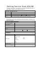
Getting Service from ADLINK Customer Satisfaction is top priority for ADLINK TECHNOLOGY INC. If you need any help or service, please contact us. ADLINK TECHNOLOGY INC. Web Site http://www.adlinktech.com Sales & Service Service@adlinktech.com TEL +886-2-82265877 Address 9F, No. 166, Jian Yi Road, Chungho City, Taipei, 235 Taiwan FAX +886-2-82265717 Please email or FAX your detailed information for prompt, satisfactory, and consistent service.
Table of Contents List of Tables.................................................................................... iii List of Figures .................................................................................. iii How to Use This Manual ................................................................. iv Chapter 1 Introduction ..................................................................... 5 1.1 1.2 Unpacking Checklist .....................................................................
2.3 2.4 2.5 2.6 2.2.9 CompactPCI Connectors P1/J1 ...........................................23 2.2.10 CompactPCI Connectors P2/J2..........................................24 PXD-3710/3710F Jumpers Setting ............................................. 25 2.3.1 Clear CMOS.........................................................................25 2.3.2 CF1 Master Slave Selection.................................................26 2.3.3 COM1 Operation Mode Selection.........................................
List of Tables Table 1: Peripheral Connectivity Table.................................................. 16 Table 2: VGA Connector Pin Assignment ............................................. 20 Table 3: USB Connector Pin Assignment.............................................. 20 Table 4: Ethernet Connector Pin Assignment ....................................... 20 Table 5: LED Indicators Definition on the Ethernet Connector .............. 20 Table 6: Parallel Port Pin Assignment ............................
How to Use This Manual This manual is intended to assist users to configure the PXD-3710/3710F 3U system controller. It is divided into 5 chapters: Chapter 1 Introduction Overview of product features, applications, and specifications. Chapter 2 Connectors and Jumpers Outlines all connectors and provides pin definitions. Chapter 3 Getting Started Provides a summary to setup an operating system using the PXD-3710/3710F, including hardware installation and BIOS overview.
1 Introduction The PXD-3710 series is an OEM version 3U system controller from ADLINK that supports an LCD interface and extra USB ports on the rear I/O transition module. This product is designed to meet the highest performance requirement for embedded computing and features many new technologies such as up to 1.4GHz Pentium III CPU support, hot swappable CompactFlash cards, and Digital Vision Interface (DVI) through PXD-R3000, the rear IO transition module (RTM).
1.1 Unpacking Checklist Check the shipping carton for any visible damage. If the shipping carton and contents are damaged, notify the dealer for a replacement. Retain the shipping carton and packing materials for inspection by the dealer. Remember to obtain authorization before returning any products to ADLINK. Check for the following in the package. If there are any missing items, contact your dealer: PXD-3710/3710F module (May be equipped with CPU, RAM, and HDD at different speeds and capacities).
1.2 Features 1.2.1 PXD-3710/3710F Features Standard 3U PXI form factor PICMG 2.0 CompactPCI specification R3.0 compliant PICMG 2.1 R1.0 CompactPCI Hot Swap specification compliant Socket-370 Pentium III, Celeron, or VIA C3 CPU, FSB 100/133 (CPU frequency up to 1.4GHz) Two 144-pin SO-DIMM sockets supporting up to 512MB RAM One internal 44-pin EIDE for 2.
1.3 Functional Block Diagram The following topics overview the PXD-3710 main features as shown in the functional block diagram below.
I/O extensions, including the serial port COM2, USB port #3, graphic interface extension to DVI, and ATX power supply interface. The PXD-3710/3710F can be used in ADLINK PXI chassis, including: • • • PXIS-2556/2556T, 6-slot 3U instrument chassis PXIS-2650/2650T, 8-slot 3U instrument chassis PXIS-2680P, 8-slot 3U portable instrument chassis (New Model) NOTE: the PXD-3710F (with FDD) occupies 4 slots and cannot be adopted in PXIS-2556/2556T chassis.
1.3.5 Graphic Interfaces The Intel 815E GMCH2 chip is integrated with an AGP 2X, ACPI, and VESA compliant hyper-pipelined architecture 3D graphics engine. It shares up to 10MB, dynamically allocated from the host memory. Graphic resolutions can be up to 1600x1200 for both VGA and on-chip digital video output (DVO) interfaces.
storage device. Only one device can be connected with the IDE interface. In addition to the 40-pin IDE connector, a 4-pin power connector for external drives is also available. This feature makes OS or software installation easier than ever by simply connecting an IDE interface to the external IDE device. 1.3.7 Universal Serial Bus (USB) The Universal Serial Bus (USB) R1.1 provides a common interface to low-speed peripherals such as keyboard, mouse, speakers, printer, etc., simplifying cabling needs.
1.3.11 IEEE-1284 Parallel Port/Printer Interface The parallel I/O interface signals are routed to the DB-25 connector on the front faceplate. This port supports the full IEEE-1284 specification and provides a basic printer interface. The BIOS will initialize the parallel port as LPT1 with an ISA I/O base address of 378h. This default configuration also assigns the parallel port to IRQ7. The printer interface mode (Normal, Extended, EPP, or ECP) is selectable through the BIOS menu. 1.3.
1.4 Specifications General CompactPCI Features PICMG 2.0 CompactPCI specifications R3.0 compliant PICMG 2.1 R1.0 CompactPCI Hot Swap specifications compliant CPU Supports Socket370 CPUs up to 1.
IEEE 802.
Shock: 15G peak-to-peak, 11ms duration, non-operation Vibration: Non-operation: 1.88GRMS, 5-500Hz Operation: 0.5GRMS, 5-500Hz Certifications CE, FCC HALT (temperature and vibration stress) Power Consumption Configurations Pentium-III 1.4G Celeron 600 Note: +5V 7A 4.2A +3.3V 3.5A 3.5A +12V 560mA 560mA -12V 10mA 10mA The above power requirement values are measured on the PXD-3710 with a CPU, a CPU fan, 512MB RAM, one mouse, one keyboard, one internal 20GB slim-type HDD and one external 20GB HDD.
1.
2 Jumpers and Connectors This chapter provides information about the board outline, connector definitions, and jumper settings to allow users to get familiar with the PXD-3710 before getting started.
2.1 PXD-3710/3710F Board Outline and Illustratoin 2.1.1 PXD-3710/3710F Front View Optional FDD 40-pin IDE COM1 PRN LED VGA Hot Swappable CompactFlash USB CF Access LED Fast Ethernet Power Output Ejector Keyboard Mouse PXD-3710 PXD-3710F (With FDD option) Figure 2: PXD-3710/3710F Front View 2.1.
2.1.3 DB-3710L2 Daughter Board Battery Socket Internal FDD Connector CF Socket CF Master/Slave Setting Jumper CN7 Figure 4: DB-3710L2 Daughter Board 2.1.
2.2 PXD-3710/3710F Connector Pin Assignments 2.2.1 VGA Connector Signal Name Red Blue GND GND N.C. N.C. HSYNC NC Pin 1 3 5 7 9 11 13 15 Pin 2 4 6 8 10 12 14 Signal Name Green N.C. GND GND GND N.C. VSYNC Table 2: VGA Connector Pin Assignment 2.2.2 USB Connectors Port 1 Port 2 Pin 1 Pin # 1 2 3 4 Signal Name Vcc USBUSB+ Ground Table 3: USB Connector Pin Assignment 2.2.
2.2.
2.2.6 COM1 Serial Ports (RS-232/422/485) The PXD-3710/3710F COM1 serial port can be configured as RS232, RS422 or RS485 by setting the appropriate jumpers. Refer to section 2.3.3.
2.2.9 CompactPCI Connectors P1/J1 Pin A B C REQ64# (1) D E +5V J1-24 AD[1] +5V J1-23 +3.3V AD[4] AD[3] +5V AD[2] J1-22 AD[7] GND +3.3V AD[6] AD[5] GND J1-21 +3.3V AD[9] AD[8] GND C/BE[0]# GND J1-20 AD[12] GND NC AD[11] AD[10] GND J1-19 +3.3V AD[15] AD[14] GND AD[13] GND J1-18 SERR# GND +3.3V PAR C/BE[1]# GND J1-17 +3.3V (3) GND PERR# GND J1-16 DEVSEL# GND NC STOP# LOCK# GND J1-15 +3.
2.2.
2.3 PXD-3710/3710F Jumpers Setting The PXD-3710/3710F is designed for maximum flexibility with as few jumpers as possible. Most of the configuration options can be selected through the BIOS menu. However, some options still need to be configured by jumpers. Note. There is no jumper for front side bus (FSB) or CPU frequency selection. The FSB and CPU frequency are set by auto-detection. The PXD-3710/3710F is assembled with 3 boards including a main board and two daughter boards.
2.3.2 CF1 Master Slave Selection CF1 master/slave DB-3710L2 CN7 3 2 1 CF1 Master 2-3 (Default) 3 2 1 CF1 Slave 1-2 Table 16: CF1 Master/Slave Jumper The CF1 Master/Slave jumper allows the selection of the CF card to be configured as either a master or slave IDE device if there is more than one storage device installed in the system. 2.3.
2.4 PXD-R3000 Board Outline and Illustratoin 2.4.1 PXD-R3000 Component side View Figure 6: PXD-R3000 Component Side View 2.4.
2.5 PXD-R3000 Connector Pin Assignments 2.5.
2.5.3 DVI Connector CN4 1 8 C1 Pin 1 2 3 4 5 6 7 8 C2 9 17 24 C3 C4 C1~C4 Signal TX2TX2+ GND NC NC NC NC NC NC (1 Pin 9 10 11 12 13 14 15 16 Signal TX1TX1+ GND NC NC +5V GND HPDET Pin 17 18 19 20 21 22 23 24 Signal TX0TX0+ GND NC NC GND TXC+ TXC- C5 GND M1, M2 CGND Table 20: DVI connector Pin Definition Note 2.6 1: No support for RGB (Analog) Signals (DVI-I) PXD-R3000 Jumper Setting 2.6.
3 Getting Started This chapter gives a summary of what is required to setup an operating system using the PXD-3710/3710F. Hardware installation and BIOS overview are also discussed. Note that the PXD-3710/3710F is shipped with CPU, RAM and HDD preinstalled. The installations of the CPU, RAM, and HDD are done in an ADLINK factory and the procedures described in the following sections are for users’ reference.
PXD-3710/3710F main board and DB-3710L2 daughter board, so we recommend that users have RAM installed professionally by ADLINK. For applications requiring the memory other than the standard 128MB, please contact a local ADLINK dealer for details. 3.3 HDD and CF Installation The PXD-3710/3710F is equipped with a set of slim-type HDD mounting brackets where a 2.5 inch IDE drive can be seated. A 20GB HDD is installed by default.
3.3 BIOS Configuration Overview On the PXD-3710/3710F BIOS, ADLINK provides the following key features: PCI Plug and Play support DMI BIOS Support: Desktop Management Interface (DMI) allows users to download system hardware-level information such as CPU type, CPU speed, internal/external frequencies, and memory size. Green Function: Power management via the BIOS, activated through selectable power manager events.
3.4 Operating System Installation For more detailed information about the operating system, refer to the documentation provided by the operating system vendor. PXI/CompactPCI devices are automatically configured by the BIOS during the boot sequence. Most operating systems require initial installation on a hard drive from a floppy or a CD-ROM drive. These devices should be configured, installed, and tested with the supplied drivers before attempting to load the new operating system.
4 Driver Installation 4.1 Hardware Configuration File Installation This section describes system requirements of the Intel 815E chipset device drivers. The drivers are designed for and tested with Windows 98/2000/XP. The system must contain a supported Intel processor and chipset configuration. Ensure that a mouse is connected to the system. One of the following versions of Windows 98/2000/XP must be installed on the system prior to running utility program.
SETUP.EXE Insert the ADLINK All-In-One CD, run X:\PXI_Platform\PXI Controller\PXI-3710_3710F\Chipset\I815\Win9x2k\Disk1 (where X is the CD-ROM drive). at Click 'Next' on Welcome Screen to read and agree to the license agreement. Click Yes if you agree to continue. NOTE: If you click No, the program will terminate. Click 'Finish' to restart the system when prompted to do so. Follow the screen instructions and use default settings to complete the setup when Windows is restarted.
4.2 VGA Drivers Installation This section describes the VGA driver installation for the on-board VGA controller Intel 815E GMCH2. The relative drivers are located in X:\PXI_Platform\PXI Controller\PXI-3710_3710F\815E VGA Drivers of the ADLINK All-In-One CD, where X: is the drive letter of the CD-ROM drive. The VGA drivers for Windows 98, Windows NT, and Windows 2000/XP are included. Windows 98/2000/NT/XP may try to install the standard VGA driver.
Novell Netware, DOS Setup for Novell NetWare DOS All the above drivers are included in the ADLINK All-In-One CD. In the following section, driver installation for Windows 2000/XP, Windows 98 and Windows NT are outlined. For driver installation of non-Windows Operating Systems, refer to the readme file in the following path location. X:\PXI_Platform\PXI Controller\PXI-3710_3710F\LAN\100PDisk 4.3.2 LAN Driver Installation on Windows 2000/XP Windows 2000/XP will attempt to install a LAN driver automatically.
4.3.3 LAN Driver Installation on Windows 98 Windows 98 will attempt to install a LAN driver automatically. To guarantee compatibility, manually install the latest LAN driver, which is stored in the ADLINK All-In-One CD. After installing Windows 98, update to the new driver by following these procedures: 1. Boot Windows 98, Click Start. Select Settings then double-click the Control Panel option. 2. Double-click on the System icon, and then click on the Device Manager tab. 3.
4.3.4 LAN Driver Installation on Windows NT Windows NT may ask to install a LAN driver from its own library of drivers. We recommend you to manually update the LAN driver, located on the ADLINK All-In-One CD, to guarantee compatibility. After installing Windows NT, please update the drivers by the following procedures: 1. From the Control Panel, double-click the Network icon, a Network Configuration window pop up, click Yes. 2. In Network Setup Wizard, click Next>, click Select From List… button. 3.
5 Utilities This chapter explains extended functions of the PXD-3710/3710F controller, including watchdog timer, Intel Pre-boot Execution Environment (PXE), and hot swap introduction. 5.1 Watchdog Timer Overview The primary function of the watchdog timer is to monitor the PXD-3710’s operation and take corrective action if the software fails to function as programmed.
The PXD-3710’s custom watchdog timer circuit is implemented in a programmable logic device. The watchdog timer contains a "Control and Status Register." The register allows the BIOS or user application to determine if a watchdog time out was the source of a particular reset. The watchdog timer drives the First and Second Stages as follows: • The watchdog times out (First Stage) after a selected timeout interval. • NMI or INIT (software selectable) is driven high. • A hard reset occurs (Second Stage).
(2) Reboot the system. You can also write your own DLL by referring to the DOS sourced ADLINK has provided. 5.2 Intel Preboot Execution Environment (PXE) The PXD-3710/3710F series supports the Intel Pre-boot Execution Environment (PXE), which provides the capability of boot-up or executing an OS installation through Ethernet ports. There should be a Windows NT or Windows 2000 DHCP server in the network with one or more servers running PXE and MTFTP services.
5.3 PICMG 2.1 Hot Swap Support The PXD-3710/3710F Hot-Swap capability allows non-system slot boards to be added or removed while the system is powered up. PXD-3710/3710F provides independent clocks for each slot and accesses to the ENUM# signal on the backplane, which are compatible with PICMG 2.1 Hot Swap Specification. However, the PXD-3710/3710F itself is not hot swappable.
Warranty Policy Thank you for choosing ADLINK. To understand your rights and enjoy all the after-sales services we offer, please read the following carefully: 1. Before using ADLINK’s products please read the user manual and follow the instructions exactly. 2. When sending in damaged products for repair, please attach an RMA application form. 3. All ADLINK products come with a two-year guarantee, repaired free of charge. The warranty period starts from the product’s shipment date from ADLINK factory.
RMA Request & Confirmation Form Dear Customer, Page 1 of 2 Please fill out and fax back this form to obtain the RMA number for your returned or repaired product. Thank you very much! Your Company Name : Your Name : Invoice No. : Part No. Qty. Serial No. ADLINK RMA #: 46 • Warranty Policy The reason of defect Received Qty.
Page 2 of 2 Note: 1. Please give specific details of the defect. Do not give general reasons like, “not working, error, dead, etc. “ 2. Please ship prepaid by Speed post (EMS) (If items are shipped via freight forwarder, we will not cover the extra handing charges) 3. Please show a value of US$10 for each item and include the RMA number. Also, be sure to write on shipping invoice, “for repair, no commercial value” for customs.