
User's Manual
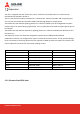

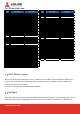

Table Of Contents

DOC#NCP-R4600 GEN2-SOW
Expansion
The unit is equipped with four mPCIe slots, two m.2 slots from I/O board and one m.2 slot from the
motherboard as detailed in Section 2.
Two m.2 slots from the modem area (Section 5.1 location M.2-1 & M.2-2) provide USB 3.0 signaling and
one m.2 from the motherboard provides USB3.0 and SATA signaling for a storage device.
Two mPCIe slots with USB 3.0 signaling (Section 5.1 mPCIe-3 & mPCIe-4) will be configurable to support
isolation of pins 22, 28 and 48 using dipswitches, this is to allow fitment of modems requiring these pins to
be left open.
Two mPCIe slots with USB 2.0 and PCIe x1 signaling (Section 5.1 mPCIe-5 & mPCIe-6) will follow PCIe mini
card spec V1.2.
The expansion slot pin outs have been designed to support mPCIe USB3.0 and M.2 USB3.0.
Installation of internal m.2 storage slot will require removal of the chassis covers. To help prevent damage
to the screw head, a torx fitting will be used Torx type M3, F HEAD, L5 and their locations are shown in the
chassis underside view under the mechanical drawings section.
Slot Location Signal
M.2 I/O board (AFM) USB 3.0
M.2 I/O board (AFM) USB 3.0
mPCIe I/O board (AFM) USB 3.0
mPCIe I/O board (AFM) USB 3.0
mPCIe I/O board (AFM) USB 2.0, PCIe x1
mPCIe I/O board (AFM) USB 2.0, PCIe x1
M.2 Motherboard (MB) SATA, USB3.0
1.2.1 Pin-out of mini PCIe slots