BattMan Smart Battery Management Reference System Manual Revision: 2.
Revision History Page 2 Release Date Change 2.
Preface Copyright 2010 ADLINK Technology, Inc. This document contains proprietary information protected by copyright. All rights are reserved. No part of this manual may be reproduced by any mechanical, electronic, or other means in any form without prior written permission of the manufacturer. Disclaimer The information in this document is subject to change without prior notice in order to improve reliability, design, and function and does not represent a commitment on the part of the manufacturer.
Environmental Responsibility (RoHS & WEEE) ADLINK is committed to fulfill its social responsibility to global environmental preservation through compliance with the European Union's Restriction of Hazardous Substances (RoHS) directive and Waste Electrical and Electronic Equipment (WEEE) directive. Environmental protection is a top priority for ADLINK.
Conventions Take note of the following conventions used throughout this manual to make sure that users perform certain tasks and instructions properly. Additional information, aids, and tips that help users perform tasks. Information to prevent minor physical injury, component damage, data loss, and/or program corruption when trying to complete a task. Information to prevent serious physical injury, component damage, data loss, and/or program corruption when trying to complete a specific task.
Important Safety Instructions For user safety, please read and follow all instructions, warnings, cautions, and notes marked in this manual and on the associated equipment before handling/operating the equipment. f Read these safety instructions carefully. f Keep this user’s manual for future reference. f Read the specifications section of this manual for detailed information on the operating environment of this equipment.
Technical Support Contact us should you require any service or assistance. ADLINK Technology, Inc. Address: 9F, No.166 Jian Yi Road, Chungho City, Taipei County 235, Taiwan קᗼխࡉؑ৬ԫሁ 166 ᇆ 9 ᑔ Tel: +886-2-8226-5877 Fax: +886-2-8226-5717 Email: service@adlinktech.com Ampro ADLINK Technology, Inc. Address: 5215 Hellyer Avenue, #110, San Jose, CA 95138, USA Tel: +1-408-360-0200 Toll Free: +1-800-966-5200 (USA only) Fax: +1-408-360-0222 Email: info@adlinktech.com ADLINK Technology (China) Co., Ltd.
ADLINK Technology (Europe) GmbH Address: Nord Carree 3, 40477 Duesseldorf, Germany Tel: +49-211-495-5552 Fax: +49-211-495-5557 Email: emea@adlinktech.com ADLINK Technology, Inc. (French Liaison Office) Address: 15 rue Emile Baudot, 91300 Massy CEDEX, France Tel: +33 (0) 1 60 12 35 66 Fax: +33 (0) 1 60 12 35 66 Email: france@adlinktech.com ADLINK Technology Japan Corporation Address: 151-0072 ᧲੩ㇺᷦ⼱ᐈ䊱⼱㩷 1-1-2 ᦺᣣ↢ᐈ䊱⼱䊎䊦 8F Asahiseimei Hatagaya Bldg.
Table of Contents Preface ............................................................................................................................ 3 Important Safety Instructions .......................................................................................................... 6 Technical Support ............................................................................................................................ 7 1 Introduction ...........................................................
This page intentionally left blank.
1 Introduction ADLINK’s BattMan (Battery Management) module is a Smart Battery Management System that supports two Smart Batteries and provides ATX power for a mobile embedded system.
2 Electrical Specification The Battman module is a single or dual Smart Battery Manager. The module supports a standard 2.5 mm DC Input Jack for connection of a standard 19V AC/DC power adapter. The battery charger output voltage is configurable to adapt it to battery packs consisting of 2, 3, 4 or 5 Li-ion battery cells*. The module can work in either notebook mode (ACPI) or as stand-alone battery charger.
3 Functional Block Diagram The BattMan module provides 12V and 5Vsb to the COM Express Carrier Board and 12V and 5V to the Auxiliary Power connector to support a storage device. The BattMan module communicates with the COM Express host system via the Host SMBus interface. The BattMan module acts as a slave and the COM Express module sends commands to the BattMan module to get information.
84.71 4 Mechanical Dimensions 14.93 121.
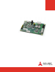
5 Component Locations BattMan 51-79201- CN1 CNX2 CNX3 JP2 JP1 CN6 LED4 LED1 LED2 LED3 CN2 CN5 CNX1 CNX4 Connector Function CN1 CN2 CN5 CN6 CNX1 CNX2 CNX3 CNX4 JP1 JP2 19V AC/DC Power Adapter Input Low Battery Voltage Trip Threshold Jumper Maximum Charge Voltage Jumper Host Control/Monitor Connector Auxiliary Output Power Connector ATX Output Power to Host System Connector Battery 1 Connector Battery 2 Connector Operating Mode Jumper Charger Enable/Disable Jumper Express-CB Express-IA533 User’s
6 Module Configuration 6.1 Operating Mode The BattMan module supports two operating modes that are configurable by jumper setting: f Battery Management Mode - connects with the COM Express host system via the Host SMBus interface to function as a Smart Battery Management System f Stand-alone Charger Mode - acts as a stand-alone charger for two Smart Batteries The operating mode is set using jumper JP1. 6.
6.3 Indicator LEDs There are four LEDs to indicate the Operating Mode and Charger Status of the BattMan module. The functions of LED1~4 are dependent on the settings of JP1 and JP2. When in Battery Management Mode (JP1 pins 1-2 shorted), LED1/LED2 are connected to the Host SMBus clock and data signals and are ON to indicate that the BattMan module is actively communicating with the Host System.
6.4 Battery Settings The BattMan module has been designed to provide power to COM Express systems using battery packs having 2, 3, 4 or 5 Li-ion cells in series.
7 Connector Pin Assignments 7.1 ATX Output Power to Host System Connector (CNX2) 12V and 5Vsb supply to COM Express host system 7.2 +5 VSB +5 VSB +12 V +12 V +12 V 1 2 3 4 5 6 7 8 9 10 Auxiliary Output Power Connector (CNX1) 1 2 Power supply to peripheral devices such as harddisks 7.
7.4 Battery 1 Connector (CNX3) Interface between Battman and Smart Battery 1 7.
8 Getting Started This chapter describes how to connect the BattMan Smart Battery Reference System to power a COM Express system and access the battery power subsystem information under Windows OS. 8.
8.2 Cable Connections The BattMan module connectors are shown in the diagram below. 19V DC Power to Carrier Board SMBus to Host System Battery 1 Auxilary Power Battery 2 Be sure to set JP1 and JP2 to the correct settings for your battery packs before connecting the AC adapter to the BattMan module. See Section 6.4 Battery Settings. 1. Connect the ATX Power output of the BattMan module (CNX2) to the ATX power input of the COM carrier board using the 10-pin to 24-pin ATX cable provided. 2.
The figure below shows a BattMan Smart Battery Reference System connected to an Express-BASE carrier board with COM Express module and SATA hard drive. AC Adapter ATX Power SMBus Aux.
8.3 Windows OS Interface Device Presence ADLINK's system BIOS fully supports the BattMan Smart Battery Reference System and reports the presence of a Smart Battery device to the OS. In Windows, the battery power subsystem information is listed in the Device Manager under the "Batteries" category. The system BIOS will check the current system configuration and then report back to the OS. There are three possibilities for the battery report information.
Battery State Notification The system BIOS is notified of the state of the battery power subsystem (AC power or battery mode) when it receives an SMBALERT# as a SCI event. An alert may be sent to update the charging state, remaining battery capacity, or presence of an AC adapter. The OS can also query the system BIOS to update the battery power information. Placing the cursor over the battery state icon will cause the OS to update the battery power information.
9 References Following specifications are used for reference to develop the smart battery management support for ADLINK Computer-on-Module (COM) products. f Advanced Configuration and Power Interface Specification, Revision 3.0. f Smart Battery Charger Specification, Revision 1.1. f Smart Battery Data Specification, Revision 1.1 f Smart Battery Selector Specification, Revision 1.1. f Smart Battery System Manager Specification, Revision 1.0 Release Candidate b.
This page intentionally left blank.