NuIPC cPCIS-1000/2000 Series: 3U CompactPCI Sub-systems and Components User’s Guide Recycled Paper
This user’s manual includes the information for the following products range: Sub-systems: (Single System with LCD) • cPCIS-2150: 3U CompactPCI Platform with LCD and Off-the-Shelf ATX PSU • cPCIS-2151: 3U CompactPCI Platform with LCD and Universal AC PSU • cPCIS-2152: 3U CompactPCI Platform with LCD and Dual Redundant AC PSU • cPCIS-1151: 3U CompactPCI Platform with LCD and Universal AC PSU Sub-systems: (Single System without LCD) • cPCIS-2100: 3U CompactPCI Platform with Off-the-Shelf ATX PSU • cPCIS-2102:
u LCD Kit: • cPCI-LCD: High brightness 6.
Copyright 2000 ADLINK Technology Inc. All Rights Reserved. Manual Rev. 1.02: August 30, 2000 The information in this document is subject to change without prior notice in order to improve reliability, design and function and does not represent a commitment on the part of the manufacturer.
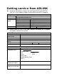
Getting service from ADLINK u Customer Satisfaction is always the most important thing for ADLINK Tech Inc. If you need any help or service, please contact us and get it. ADLINK Technology Inc. Web Site Sales & Service Technical Support TEL Address u http://www.adlink.com.tw http://www.adlinktechnology.com service@adlink.com.tw NuDAQ nudaq@adlink.com.tw NuDAM nudam@adlink.com.tw NuIPC nuipc@adlink.com.tw NuPRO nupro@adlink.com.tw Software sw@adlink.com.tw +886-2-82265877 FAX +886-2-82265717 9F, No.
Table of Contents How to Use This Manual..................................................iv Chapter 1 Introduction .....................................................1 Chapter 2 Chassis.............................................................3 2.1 cPCIS-2000 Chassis ........................................................... 3 2.1.1 2.1.2 2.1.3 2.2 cPCIS-1000 Chassis ........................................................... 6 2.2.1 2.2.2 2.3 Introductions.......................................
Chapter 4 3U Backplane.................................................28 4.1 cBP-3400 Series ............................................................... 29 4.1.1 4.1.2 4.1.3 4.1.4 4.1.5 4.2 4.3 cBP-3100 Series ............................................................... 33 cBP-3200 Series ............................................................... 34 4.3.1 4.3.2 4.3.3 4.3.4 4.4 Specifications......................................................................39 PCB Drawing................
6.3.2 6.3.3 6.4 cPCIS-2102 Series............................................................ 56 6.4.1 6.4.2 6.4.3 6.5 Configurations.....................................................................54 Ordering Options ................................................................55 Features...............................................................................56 Configurations.....................................................................56 Ordering Options ..........................
How to Use This Manual This manual is designed to help you use the cPCI-2000/1000 Series 3U CompactPCI Sub-system. It is divided into five chapters: u Chapter 1, "Introduction," gives an overview of the product features. u Chapter 2, "Chassis," describes the specifications and installation of the chassis. u Chapter 3, "Power Supply," describes the using of power supply. u Chapter 4, "Backplane", describes the backplane specifications. u Chapter 5, "LCD Kit", describes the specifications of 6.4” LCD kit.
1 Introduction This users manual gives you the following information about the cPCI-2000 series 3U CompactPCI sub-systems, including the brief introduction of the components and the detail specifications of the sub-systems.
• cBP-3200 Series: 3U 32-bit CompactPCI backplane with rear I/O • cBP-3052/3051: Backplane for single/dual 31-pin 3U redundant power supply • cBP-3062: Backplane for dual 47-pin 3U redundant power supply u LCD Kit: • cPCI-LCD: High brightness 6.4” LCD kit We also provide sub-systems based on the above optional components. Whenever the sub-systems cannot fully meet users’ requirement, please contact with us for discussing the possibility for more options.
2 Chassis In this chapter, we will describe the detail features and specifications of the cPCIS-1000 and cPCIS-2000 chassis. Other mechanical parts which may be used to assembly the system also be described. 2.1 cPCIS-2000 Chassis 2.1.
2.1.2 Mechanical Drawing Note: This drawing is for showing the mechanical dimension only, the components inside the chassis is dependent on every different model number . ADLINK 2.1.3 Specifications u Dimension: 444.2(W) mm x 177(H) mm x 257.9(D) mm Note : 1. Width is 482.6 mm (19”) with rack-mounting kit. 2. 177.0 mm is to fit 4U height. Total height is 189.1 mm with foot stands.
• Current control of the FAN to provide stable fan operation • Fan failure detection ready to use • Power input connector (CN101) Pin # Signal 1 -12V 2 GND 3 +5V Cable color Yellow Black Red • Connector to Fans (CN102) Pin # 1 2 3 4 5 6 7 8 Signal GND Fan #1 power GND Fan #2 power GND Fan #3 power GND Fan #4 power • Fan failure output (CN103) Pin # 1 2 3 4 5 Signal +5V Fan #1 failure output Fan #2 failure output Fan #3 failure output Fan #4 failure output • Power requirement: n +5V: 40 mA maximum n -1
2.2 cPCIS-1000 Chassis 2.2.1 Specifications u 19” rack-mount 3U in height, 21-slot CompactPCI card cage u Need external fan for cooling u Dimension: 482.56 (W) mm x 133.35 (H) mm x 250.0 (D) mm 2.2.2 Mechanical Drawing Note: This drawing is for showing the mechanical dimension only, the components inside the chassis is dependent on every different model number .
2.3 3U Power Supply Frame cPCI-PSF 2.3.1 Introductions The cPCI-PSF is a power supply frame, which is designed for holding the PS2 size power supply in a 3U CompactPCI card cage. Four standard card guides are necessary for guiding the position of this frame. Any PS2 sized power supply unit can be used together with cPCI-PSF. 2.3.2 Features u To fit standard 3U CompactPCI form factor with 9-slot (36HP) width. Dimension: 182.6 mm x 128.7 mm x 94.
2.4 3U Drive Bay Frame cPCI-DBF 2.4.1 Introductions The cPCI-DBF is a drive bay frame, which is designed for holding the FDD, HDD or CD-ROM drives in a 3U CompactPCI card cage. The drive bay can support two 5 1/4” drives and one 3 1/2” drive. 2.4.2 Features u To fit standard 3U CompactPCI form factor with 10-slot (40HP) width. Dimension: 202.9 (W) mm x 128.7 (H) mm x 172.5. (D) mm u Support two 5 1/4” drives and one 3 1/2” drive u Rugged mechanical design 2.4.3 2.
3 Power Supply Unit The power supply unit in the 3U CompactPCI system is with modular design. The users can chose the most suitable solution for the specified applications. There are many kinds of power supply unit can be installed in 3U CompactPCI card cage. In this chapter, the features and specifications of the following power supply unit or modules are shown.
3.1 cPS-150R 3.1.1 Introduction cPS-150R is a redundant power supply which designed for CompactPCI standard industrial computer. It provides hot-swappable function, and can make the output current shared in parallel. It provides good quality power and instant maintenance to a system. 3.1.2 The Outline of Power Supply Figure 3.1.2 The Outline of cPS-150R Power Supply Functions of LED POWER: The Power LED is lit Green if the AC input power has been turned on.
3.1.3 Installation After inserting cPS-150R to a standard 3U CompactPCI system or the standard 6U CompactPCI system, you can turn on the switch on the chassis. Of course, you may turn on the power switch on the chassis first, and insert cPS-150R, which delivers full safety redundant, hot-swappable function, and provides the plug-able feature.
Ripple voltage +5V............... 1.0 % p-p +3.3V............ 1.5 % p-p +12V............. 1.0 % p-p -12V ............. 1.0 % p-p Current sharing in parallel Any number of power supplies can be operated in parallel and will share current to within 10% The output voltage of +5V changes within ±3% of allowed value. Load regulation Line regulation The output voltage of +5V changes within ±0.1% of allowed value. Hold up time Rising time Temperature coefficient Protection >6ms <200ms 0.
meets EN55022 Class A EMS:EN 50082-2 EN61000-4-2 EN61000-4-3 EN61000-4-4 EN61000-4-6 EN61000-4-8 ENV 50204 Impact & vibration Frequency Range: Unpackaged, test 5Hz – 35Hz 5 min Non-operating 35Hz – 55Hz 5 min 55Hz – 5Hz 5 min Displacement: 0.38mm Dweep time: 30 minutes for each axis Duration: 2 cycles for three orthogonal axis.
3.1.5 Connector Pin Assignments Pin # (1) Column A A13 A14 A15 A16 A17 A18 A19 A20 Column B B2 B5 B8 B11 B13-18 B19 B20 B22 B25 B28 B31 Column C C13 C14 C15 C16-18 C19 C20 Staging (2) Mnemonic Description EL EL EL EL EL EL EL EL SP INH# ISH 5S5S+ 3.3V +12V −12V Spare Inhibit Signal Current Share Signal 5V Sense − 5V Sense + +3.3 VDC +12 VDC −12 VDC SL SL EL SL SL SL EL EL EL EL ACL ACN CG (3) 3.3V +12V −12V 5V GND +DC −DC AC Line AC Neutral No Pin Loaded Chassis Ground +3.
Definitions of Pin Signals Signal INH# Definition Inhibit signal MAY be used to “turn off” the power supply outputs. This signal is on a longer pin than the EN#(enable) signal and therefore has precedence over the EN# signal when determining power supply operation (see table below). The INH# signal is typically connected to an “ON/OFF” switch. This signal is optional.
Caution: Improperly connected 5S+ and 5S- leads may damage the power supply.
3.2 cPS-175 Series Power Supply Unit 3.2.1 Introduction cPS-175 series products are a power supply designed for CompactPCI standard industrial computer. Based on the CompactPCI standard design, it has hot-swappable function, and can make the output current shared in parallel. It provides good quality power and instant maintenance to a system. They are compliant with the PICMG 2.11 specifications. 3.2.2 The Outline of Power Supply 3.2.
There are two external warning LEDs. POWER: The Power LED is lit green if the AC or DC external power input power has been turned on. FAULT: If LED is with light, it indicates that the power unit is defective. It means the input voltage is out of the range, or over temperature, over current, or short circuit. 3.2.4 Specifications Input Item Voltage Input Current Inrush Current Frequency Power Factor Efficiency Protection cPS-175/AC 90 – 264 Vac <5A <40A @ 240V AC 50 – 60 Hz 0.
Temperature Coefficient Protection 0.05% / °C 1. All outputs protected against overload and short circuit. Straightline current limiting, does not fold-back or latch-up during startup or load transients. Automatic recovery. 2. Shutdown at internal heatsink temperature of 95°C. Automatic recovery. 3. Shutdown at the output voltage exceeds the nominal voltage 20%. Recycle power to reset.
Operating Area 100 forced air 15 cfm 50 0 0 10 20 30 40 50 60 70 20 • Power Supply Unit Ambient °C
3.2.3 Connector Pin Assignments The Type of Connector 47 46 45 42 43 39 40 36 37 33 34 30 31 27 28 24, 25 21 22 19 17 15 13 11 9 7 5 3 1 44 41 38 35 32 29 26 23 20 18 16 14 12 10 8 6 4 2 Positronic Industries Part Number: PCI47M400A1 or PCIH47M400A1.
Definitions of Pin Signals Signal EN# INH# Definition Enable signal should be used to "turn on" the power supply outputs. EN# is used in conjunction with INH# (see Table 2.1) and is typically connected to ground to enable the power supply after other signals on longer pins have made contact. Inhibit signal should be used to "turn off" the power supply outputs.
input for DC input power supplies. Front panel keying is provided to prevent damaging an AC power supply inserted into a backplane wired for DC and vice versa. CGND Chassis GND signal shall be connected to safety ground with a low impedance connection. V1ADJ V1 output voltage may be margined up to +10% if V1ADJ input is pulled to RTN or -10% if pulled to V1 using a programming resistor network. Typically usage is Rt=10KO . See Figure 2.1.
3.3 APS-925AX: 280 ATX Power Supply 3.3.1 Introductions The APS-925AX switching power supply is ideal for use in ATX computers, workstations or equivalent systems. This power supply can be installed with the cPCI-PSF as a 3U CompactPCI power supply module. 3.3.2 Specifications u AC Input Characteristics AC Input voltage is switching automatically according to AC input voltage. The acceptable input voltage range is as following table.
Line regulation The output line regulation for each output is less than +-1% while measuring at rated load and +-10% of 115VAC or 230VAC input voltage changing. u Load regulation The output voltage load regulation is less than the values in the following table by changing each output load +-40% from 60% rated load, and keep all other outputs at 60% rated load. Voltage +5V Regulation +/-3% +3.
• Operating temperature: 0°C to 70°C When the ambient temperature is over 40°C (115V/230V) , the output power should be de-rated as following curve: • Storage temperature: -40°C to +75°C • Operating humidity: The power supply can operate from 5% humidity to 95% humidity non-condensing at 40°C u Regulatory Agency Certification • Safety standards: Designed to meet the following standards: UL 1950 CSA 22.2 NO.
4 3U Backplane In this chapter, specifications of many 3U backplane options will be included: • cBP-3400 series: 64-bit 3U CompactPCI backplane • cBP-3100 series: 32-bit 3U CompactPCI backplane with optional DIN socket • cBP-3200 series: 32-bit 3U CompactPCI backplane with rear I/O option Please refer the each section for detail product list of every series.
4.1 cBP-3400 Series 4.1.1 Features u CompactPCI PICMG 2.0 R2.1 compliant u Support 3U, 64-bit CompactPCI bus on P1 and P2, support 7-bus mastering I/O slots u Number of slots: 8/6/4 slots (include systems slots) u 10 layers PCB for accurate impedance control u Optional DIN plug-in socket for plug-in power supply u Support ATX, PS2 and screw terminals for DC power input connector 4.1.
4.1.3 PCB Drawing 1 2 3 4 5 6 7 8 J1 7 6 5 4 3 2 1 sys 8 7 6 5 4 3 2 1 sys 1 2 3 4 5 6 7 CN4 4.1.4 Specifications u Compliant to CompactPCI PICMG 2.0 R2.1 specifications u Standard 3U form factor u Four power input connectors: ATX, PS2, screw terminal, plug-in PSU input connectors u V(I/O) selectable from +5V or +3.3V.(default +5V) u Dimension: 133.35 mm x 243.8 mm x 3.2 mm (3U height, 12-slot width) 4.1.
u CN1: Standard ATX DC Power input connector Signal Pin No. Pin No. Signal +3.3V 1 11 +3.3V +3.3V 2 12 -12V GND 3 13 GND +5V 4 14 PS_ON GND 5 15 GND +5V 6 16 GND GND 7 17 GND PWR_OK 8* 18 -5V +5V SB 9* 19 +5V Sense +12V 10 20 +5V u CN2: Standard PS2 DC Power input connector u CN3: General Purpose screw terminals CN3 Pin # Name 1 FAL# 2 DEG# 3 -12V 4 +12V 5 GND 6 +5V 7 V(I/O) 8 +3.3V 9 GND 10 +5V u J1: Compliant the 31-pin CompactPCI power supply interface standard of the PICMG 2.11.
Signal GND GND GND GND GND GND GND Pin No. Pin No. 1 2 3 4 5 6 7 8 9 10 11 12 13 14 Signal +5V DEG# FAL# INH# PRST# +5V +12V Please note that to short the pin #7 and pin #8 can disable the DC power output from CN2 CompactPCI power interface.
4.2 cBP-3100 Series The cBP-3100 series products are with the same PCBs as the cBP-3400 series products. The only difference is that the P2 of the I/O slots are removed for cost reduction. All the other features are exactly the same as the cBP-3400 series products.
4.3 cBP-3200 Series 4.3.1 Features u Compliant to CompactPCI PICMG 2.0 R2.1 specifications u Support standard 3U form factor u 32-bit CompactPCI bus on P1, support 7-bus mastering I/O slots u Optional P2 with rear I/O capability u Support ATX and screw terminals for DC power input connectors u V(I/O) selectable from +5V or +3.3V. u 10 layers PCB for accurate impedance control u Dimension: 133.35 mm x 182.0 mm x 3.2 mm (3U height, 9-slot width) 4.3.
4.3.
cBP-3208R:with P2 rear I/O 1 3 4 5 6 7 8 Rear I/O Rear I/O Rear I/O Rear I/O Rear I/O Rear I/O Rear I/O Rear I/O Front view 2 7 6 5 4 3 2 1 sys 8 7 6 5 4 3 2 1 sys 1 2 3 4 5 6 7 Rear view 4.3.4 Connectors pin assignments u P1 & P2 of system slot: Standard 32-bit CompactPCI specifications of the PICMG 2.0 R2.1 specifications u P1 of I/O slot: Standard 32-bit CompactPCI specifications of the PICMG 2.0 R2.
Signal +3.3V +3.3V GND +5V GND +5V GND FAL# DEG# +12V Pin No. Pin No. Signal 1 11 +3.3V 2 12 -12V 3 13 GND 4 14 INH# 5 15 GND 6 16 +5V Sense7 17 GND 8* 18* JP7 9* 19 +5V Sense+ 10 20 +5V u General Purpose screw terminals Position (from top to bottom) 1 2 3 4 5 6 Name +3.3V V(I/O) +5V GND +12V -12V Note: that the V(I/O) must be shorted to either +3.3V or +5V. The default factory setting is to shorted at +5V. u JP8 INH#: DC power inhibit signal It is for inhibiting the ATX power supply.
u JP7 +12V Sense: +12V Sense Jumper JP7 Pin # Name 1 From pin #18 of CN1/CN2 2 Connect to +12V Sense When the normal ATX power supply is used, the pin #18 of CN1/CN2 is with –5V power, please let this jumper open. When 31-pin CompactPCI power supply is used, this pin is not used and this jumper should be left open. When 47-pin CompactPCI power supply is used, the +12V sense is usable, therefore, the jumper can be shorted to provide this signal.
4.4 cBP-3052E Backplane 4.4.1 Specifications u Compliant with 31-pin CompactPCI power standard of PICMG 2.11 u Support two 3U redundant power supply unit u With external AC power input screw terminal u With two ATX DC output connectors u Dimension: 133.35 mm x 81.0 mm x 3.2 mm (3U height, 4-slot width) 4.4.2 PCB Drawing Front view 4.4.4 Rear view Connectors pin assignments u J1 & J2: Standard 31-pin CompactPCI power supply sockets, compliant with PICMG 2.
Note: Pin #8, #9, and #18 are not standard ATX power definition. u CN5: Screw terminals for external AC input power lines u CN7: Screw terminals for GND (CN8, CN9, CN10 are not installed.) u CN13: Screw terminals for +5V (CN14 is not installed) u CN15: Screw terminal for +12V u CN16: Screw terminal for -12V is not installed. u CN11, CN12: Screw terminals for +3.
4.5 cBP-3051 4.5.1 Specifications u Compliant with 31-pin CompactPCI power standard of PICMG 2.11 u Support one 3U plug-in power supply unit u With external AC power input screw terminal u With one ATX DC output connectors 4.5.2 PCB Drawing Front view 4.5.3 Rear view Connectors pin assignments u J1: Standard 31-pin CompactPCI power supply sockets, compliant with PICMG 2.11 specifications u CN1: ATX-like power output connector Signal Signal Pin No. Pin No. +3.3V 1 11 +3.3V +3.
Note : Pin #8, #9, and #18 are not standard ATX power definition. u CN5: AC power lines (include AC LINE, AC NEUTRAL, Chassis GND) u J4 INH#: DC power inhibit signal It is for inhibiting the ATX DC power supply output. This connector can be used for power-on switch. J4 Pin # 1 2 Name INH# GND u J3 ISH: +5V current sharing signal, this connector is used only when more than two cBP-3051 backplanes are used in one system.
4.6 cBP-3062 Backplane 4.6.1 Specifications u Compliant with 47-pin CompactPCI power standard of PICMG 2.11 u Support two 3U redundant power supply unit u With external AC power input screw terminal u With two ATX DC output connectors u Dimension: 133.35 mm x 81.0 mm x 3.2 mm (3U height, 4-slot width) 4.6.2 PCB Drawing Rear view Front view 4.6.3 Connectors pin assignments u CN101 & CN102: Standard 47-pin CompactPCI power supply sockets, compliant with PICMG 2.
u CN104 extended connector for power sharing Signal V2SENSE V2 GND V1 GND V1 GND FAL#2 DEG#2 V3 Pin No. Pin No. 1 11 2 12 3 13 4 14 5 15 6 16 7 17 8* 18* 9* 19 10 20 Signal V2 V4 GND INH# GND SRTN GND V3SENSE V1SENSE V1 Note: 1. Pin #8, #9, and #18 are not standard ATX power definition. 2. V1=+5V; V2= 3.3V; V3 = +12V; V4=-12V u CN105 INH#: DC power output inhibit signal. It is for inhibiting the DC power supply. This connector can be used for power-on switch.
5 LCD Kit 5.1 Features u High Brightness 6.4 inches TFT LCD u Modular design for easy mounting on any 3U CompactPCI Chassis u Integrated with back light inverter u Two back-light lamps with 15000 hours long life time u Optional touch screen with internal RS-232 interface 5.
5.3 Specifications u Dimension: 3U height x 10-slot (40HP) width u Screen Size: 6.4 inches (diagonal) u Resolution: 640 x 480 x 18-bit colors (262,144 colors) u Pixel pitch: 0.203 mm x 0.203 mm u High brightness 300 cd/m2 u Lamp life time: 15,000 hours @ 25°C u Integrated with back light inverter u Power requirement: • 5V @ 6.
5.
LCD Signal Extension Connector for cPCI-8217 58 57 2 1 Signal Name +12V GND +5V ENPVEE PD0 PD2 PD4 PD6 PD8 PD10 PD12 PD14 PD16 PD18 (N/C) PD20 (N/C) PD22 (N/C) GND SHFCLK M GND GND VCC NC PD24 (N/C) PD26 (N/C) PD28 (N/C) PD30 (N/C) PD32 (N/C) PD34 (N/C) Pin # 1 3 5 7 9 11 13 15 17 19 21 23 25 27 29 31 33 35 37 39 41 43 45 47 49 51 53 55 57 Pin # 2 4 6 8 10 12 14 16 18 20 22 24 26 28 30 32 34 36 38 40 42 44 46 48 50 52 54 56 58 Signal Name +12V GND +5V GND PD1 PD3 PD5 PD7 PD9 PD11 PD13 PD15 PD17 PD19
6 cPCIS-2000 Sub-systems The following sub-system’s configuration will be listed in this chapter.
6.1 cPCIS-2150 Series • cPCIS-2150 is without rear I/O connectors • cPCIS-2150R is with rear I/O connectors 6.1.1 Features • Standard 19” 3U CompactPCI form factor, 4U in height • Attached high brightness 6.
6.1.3 Ordering Options To complete the system to work, you should order an optional LCD controller card: u cPCI-8215: LCD controller card with C&T69000 (embedded 2MB RAM) u cPCI-8217: LCD controller card with SMI chipset (embedded 4MB RAM) The slot-panels with EMC gasket for the front or rear I/O cards are optional and not installed with this sub-system.
6.2 cPCIS-2151 Series 6.2.1 Features • Standard 19” 3U CompactPCI form factor, 4U in height • Attached high brightness 6.
The slot-panels with EMC gasket for the front or rear I/O cards are optional and not installed with this sub-system.
6.3 cPCIS-2100 Series • cPCIS-2100 is without rear I/O connectors • cPCIS-2100R is with rear I/O connectors 6.3.
6.3.3 Ordering Options To complete the system to work, you should order an optional ATX power supply: u APS-925AX: 280W Auto-switched AC input ATX power supply You can also fit any standard PS2 sized power supply into the slotpanels with EMC gasket for the front or rear I/O cards are optional and not installed with this sub-system.
6.4 cPCIS-2102 Series 6.4.
u cPCI-SP3E: 3U slot-panel with EMC gasket for both front I/O or rear I/O 56 • cPCIS-2000 Series Sub-systems
6.5 cPCIS-2152 Series 6.5.1 Features • Standard 19” 3U CompactPCI form factor, 4U in height • Attached high brightness 6.
u cPCI-8217: LCD controller card with SMI chipset (embedded 4MB RAM) You may specify to use cPS-175 series power supply with cBP-3061 backplane. The slot-panels with EMC gasket for the front or rear I/O cards are optional and not installed with this sub-system.
7 cPCIS-1000 Sub-systems The following sub-system’s configuration will be listed in this chapter.
7.1 cPCIS-1151 7.1.1 Features • Standard 19” 3U CompactPCI form factor, 3U in height • Attached high brightness 6.4” TFT LCD for user interface display • Attached 175W Universal AC input power supply • Using cBP-3108P backplane with 32-bit CompactPCI bus • Accept 5 I/O slots due to the available front space • Comprehensive EMC shielding 7.1.
7.2 cPCIS-1100 Series • cPCIS-1100 is without rear I/O connectors • cPCIS-1100R is with rear I/O connectors 7.2.1 Features • Standard 19” 3U CompactPCI form factor, 3U in height • Optional PS2-sized ATX power supply • Using cBP-3208 backplane with 32-bit CompactPCI bus • Accept 7 I/O slots and one system slot • Comprehensive EMC shielding • cPCIS-1100R is equipped with cBP-3208R and rear I/O card guides for rear I/O applications 7.2.
You can also fit any standard PS2 sized power supply into the controller. The slot-panels with EMC gasket for the front or rear I/O cards are optional and not installed with this sub-system.
7.3 cPCIS-1250 7.3.1 Features • Standard 19” 3U CompactPCI form factor, 3U in height • Dual systems in one system • Using cBP-3106P backplane with 32-bit CompactPCI bus for both system • Accept 5 I/O slots on each system • Comprehensive EMC shielding 7.3.
Product Warranty/Service Seller warrants that equipment furnished will be free form defects in material and workmanship for a period of one year from the confirmed date of purchase of the original buyer and that upon written notice of any such defect, Seller will, at its option, repair or replace the defective item under the terms of this warranty, subject to the provisions and specific exclusions listed herein.