CoreModuleTM 435 (PC/104 Single Board Computer) Reference Manual P/N 50-1Z085-1010
Notice Page DISCLAIMER ADLINK Technology, Incorporated makes no representations or warranties with respect to the contents of this manual or of the associated ADLINK products, and specifically disclaims any implied warranties of merchantability or fitness for any particular purpose. ADLINK shall under no circumstances be liable for incidental or consequential damages or related expenses resulting from the use of this product, even if it has been notified of the possibility of such damages.
Contents Chapter 1 About This Manual ....................................................................................................1 Purpose of this Manual ....................................................................................................................1 References ......................................................................................................................................1 Chapter 2 Product Overview...........................................................
Contents Serial Console BIOS Setup................................................................................................. 34 Hot (Serial) Cable .............................................................................................................. 34 Watchdog Timer....................................................................................................................... 35 Power Interface ..........................................................................................
Contents List of Tables Table 2-1. Table 2-2. Table 2-3. Table 2-4. Table 2-5. Table 2-6. Table 3-1. Table 3-2. Table 3-3. Table 3-4. Table 3-5. Table 3-6. Table 3-7. Table 3-8. Table 3-9. Table 3-10. Table 3-11. Table 3-12. Table 3-13. Table 3-14. Table 3-15. Table 3-16. Table 3-17. Table 4-1. Table A-1. CoreModule 435 Major Component (IC) Descriptions and Functions .................................................8 Header, Connector, and Socket Descriptions..............................................
Contents vi Reference Manual CoreModule 435
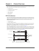
Chapter 1 About This Manual Purpose of this Manual This manual is for designers of systems based on the CoreModule™ 435 PC/104 Single Board Computer (SBC) module. This manual contains information that permits designers to create an embedded system based on specific design requirements.
Chapter 1 • About This Manual Intel Corporation and the 82541PI Gigabit Ethernet controller Data sheet: http://download.intel.com/design/network/datashts/318138.pdf NOTE 2 If you are unable to locate the datasheets using the links provided, search the internet to find the manufacturer’s web site and locate the documents you need.
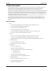
Chapter 2 Product Overview This overview presents general information about the PC/104 architecture and the CoreModule 435 Single Board Computer (SBC). After reading this chapter you should understand: • PC/104 architecture • CoreModule 435 product description • CoreModule 435 features • Major components • Header definitions • Specifications PC/104 Architecture The PC/104 architecture affords a great deal of flexibility in system design.
Chapter 2 Product Overview Product Description The CoreModule 435 SBC is an exceptionally high integration, x86-based PC compatible system in the PC/104 form factor. This rugged and high quality single board system contains all the component subsystems of a PC/AT motherboard plus the equivalent of several PC/AT expansion boards. In addition, the CoreModule 435 SBC includes a comprehensive set of system extensions and enhancements that are specifically designed for embedded systems.
Chapter 2 • • • • • Product Overview Serial Ports ♦ Provides four 10-pin headers and four buffered RS-232 serial ports with full handshaking and modem capability ♦ Provides 16C550 or 16C552 UARTs, each with a built-in 16-byte FIFO buffer ♦ Supports RS-232 or RS-485 operation on ports 1 and 2 ♦ Supports programmable word length, stop bits, and parity ♦ Supports 16-bit programmable baud-rate generator and an interrupt generator Ethernet ♦ Provides two fully independent Ethernet ports ♦ Sup
Chapter 2 Product Overview VGA Interface ♦ VGA Controller with 230 MHz triple RAMDACs for 1600 x 1200 x 85 Hz display ♦ Supports 24-bit pixel depth ♦ Interlaced or non-interlaced output TFT Interface • 6 ♦ Supports VESA Flat Panel Display interface ♦ Supports programmable panel size up to 1600x1200 pixel display resolution ♦ Supports internal VGA controller for display mode settings ♦ Supports 12-, 18-, and dual 12-bit interface (1 Pixel/Clock) ♦ Supports 3.
Chapter 2 Product Overview Block Diagram Figure 2-2 shows the functional components of the module.
Chapter 2 Product Overview Major Component (IC) Definitions Table 2-1 describes the major ICs on the CoreModule 435, and Figures 2-3 and 2-4 show the locations of the major ICs on the board. Table 2-1. Major Component (IC) Descriptions and Functions 8 Chip Type Mfg. Model Description Function CPU (U1) DMP Electronics, Inc.
Chapter 2 Product Overview Table 2-1.
Chapter 2 Product Overview - DDR2 SDRAM - System Memory - RS-232 Transceiver - COM3 - RS-422/485 Transceiver - COM1 and COM2 - 10/100/1000 Ethernet Transformer U4 U9 U2 T1 CM435_comp_bottom_a Key: U2 U4 U9 T1 Figure 2-4. Component Locations (Bottom Side) Header, Connector, and Socket Definitions Table 2-2 describes the headers, connector, and socket shown in Figures 2-6 and 2-7. Table 2-2.
Chapter 2 Product Overview Table 2-2. Header, Connector, and Socket Descriptions (Continued) J7 – Power Top 10-pin, 0.100" (2.54mm), right-angle header for Power connection J8 – GPIO (User) Top 10-pin, 0.079" (2mm) header for User defined GPIO signals J9 – Serial 2 (COM2) Top 10-pin, 0.100" (2.54mm), right-angle header for Serial 2 interface J10 – USB0 Top 5-pin, 0.100" (2.54mm), right-angle header for USB0 interface J11 – Video Top 44-pin, 0.
Chapter 2 Product Overview Key: J2 - Fast Ethernet J3 - COM1 J5 - Utility J6 - IDE J7 - Power J8 - GPIO J9 - COM2 J10 - USB0 J11 - TTL and VGA Video J13 - COM4 J14 - COM3 J17 - USB1 J19 - SPI 16 Mbit Data Storage J22 - Gigabit Ethernet LED J23 - Gigabit Ethernet JP1 - See jumper table JP2 - See jumper table JP5 - See jumper table JP6 - See jumper table JP7 - See jumper table JP8 - See jumper table P1 - PC/104 J5 J6 JP5 JP2 JP7 JP8 J14 J13 J11 JP6 JP1 J19 J3 J9 J8 J23 J17 DC AB J7 CM435_conn
Chapter 2 Product Overview Key: J12 - Compact Flash J20 - LPC J12 CM435_conn_bottom_a J20 Figure 2-7. Header and Socket Locations (Bottom Side) Jumper Header Definitions Table 2-3 describes the jumper headers shown in Figure 2-6. Table 2-3.
Chapter 2 Product Overview Key: JP1 JP2 JP5 JP6 JP7 JP8 - Serial Port 2 Termination - Serial Port 1 Termination - Backlight Voltage Select - Flat Panel Voltage Select - Compact Flash Voltage Select - IDE Select JP2 JP7 JP8 JP5 JP1 JP6 Figure 2-8.
Chapter 2 Product Overview Specifications Physical Specifications Table 2-4 shows the physical dimensions of the module and Figure 2-9 shows the mounting dimensions. Table 2-4. Weight and Footprint Dimensions Item Dimension Weight 0.10 kg. (0.20 lbs.) Height (upper surface) 11.05mm (0.435") Width 90.2mm (3.6") Length 95.9mm (3.8") Thickness CoreModule 435 NOTE 2.36mm (0.
Chapter 2 Product Overview Mechanical Specifications 3.250 0.350 0 3.775 CM435_mech_dwg_top_a 3.575 0.200 0 3.550 3.350 0.200 0 Figure 2-9. Mechanical Dimensions (Top View) NOTE All dimensions are given in inches. Black dots on vertical headers or connectors indicate pin 1 in all illustrations.
Chapter 2 Product Overview Power Specifications Table 2-5 provides the power requirements for the 300 MHz and 800 MHz versions of the CoreModule 435. Table 2-5. Power Supply Requirements Parameter Characteristics for 300 MHz CPU Characteristics for 800 MHz CPU Input Type Regulated DC voltages Regulated DC voltages In-rush Current 14.80A (74.00W) 14.86A (74.30W) Idle Power 1.30A (6.51W) 1.42A (7.12W) BIT Current (Typical) 1.32A (6.58W) 1.44A (7.
Chapter 2 18 Product Overview Reference Manual CoreModule 435
Chapter 3 Hardware Overview This chapter discusses the ICs and interfaces of the module features in the following order: • CPU • Graphics • Memory and Flash ♦ System Memory ♦ Video Memory ♦ SPI Flash • Interrupt Channel Assignments • Memory Map • I/O Address Map • Serial • USB • Utility ♦ Keyboard ♦ Mouse ♦ Battery ♦ Reset Switch ♦ Speaker • Ethernet • Video • SPI • LPC • Miscellaneous • ♦ Time of Day/RTC ♦ User GPIO ♦ Oops! Jumper (BIOS Recovery) ♦ Watch
Chapter 3 Hardware NOTE ADLINK Technology, Inc. only supports the features and options listed in this manual. The main components used on the CoreModule 435 may provide more features or options than are listed in this manual. Some of these features/options are not supported on the module and will not function as specified in the chip documentation. Only the pinout tables of non-standard headers and connectors are included in this chapter.
Chapter 3 Hardware Interrupt Channel Assignments The interrupt channel assignments are shown in Table 3-1. Table 3-1. Interrupt Channel Assignments Device vs IRQ No.
Chapter 3 Hardware Memory Map The following table provides the common PC/AT memory allocations. These are DOS-level addresses. The OS typically hides these physical addresses by way of memory management. Memory below 000500h is used by the BIOS. Table 3-3.
Chapter 3 Hardware Table 3-4.
Chapter 3 Hardware 1 2 3 4 5 9 7531 Serial Ports (J3, J9) (COM1 or COM2) Side View 10 8 6 4 2 Standard DB9 Serial Or Port Connector (Female) Rear View 6 7 8 9 CM435RS485jump_a For example, you must tie pin 3 (Rx Data –) to pin 5 (Tx Data –) and pin 4 (Tx Data +) to pin 6 (Rx Data +) at Serial Port 1 or 2 (J3 or J9) for the two-wire interface. As an alternate, you may short the equivalent pins on the DB9 connector attached to respective serial port, as shown in Figure 3-1.
Chapter 3 Hardware Table 3-6. Serial Port 3 (J14) & Port 4 (J13) Interface Pin Signals Pin # Signal DB9 # Description 1 DCD* 1 Data Carrier Detect – Indicates external serial device is detecting a carrier signal (i.e., a communication channel is currently open). In direct connect environments, this input is driven by DTR as part of the DTR/ DSR handshake. 2 DSR* 6 Data Set Ready – Indicates external serial device is powered, initialized, and ready.
Chapter 3 Hardware USB Interface The CoreModule 435 contains one root USB (Universal Serial Bus) hub and two functional USB ports. The Vortex CPU provides the USB function including the following features: • Provides one root hub with two USB ports • Supports USB EHCI v.2.0 and USB OHCI v.1.1 • Provides over-current detection status • Provides a fuse (F1, 1.
Chapter 3 Hardware Utility Interface The Utility interface provides various utility and I/O signals on the module and consists of a 10-pin, 0.1" (2.54mm) pitch header. The Vortex CPU drives the signals on the Utility interface, and Table 3-9 provides the signal definitions. • PS/2 Keyboard and PS/2 Mouse • Battery • Reset Switch • Speaker Keyboard The signal lines for a PS/2 keyboard are provided from the Vortex CPU to the Utility interface.
Chapter 3 Hardware Fast Ethernet Interface The Fast Ethernet solution originates from the Vortex 86SX/DX CPU and consists of both the Media Access Controller (MAC) and the Physical Layer (PHY) combined into a single component solution. The Vortex Fast Ethernet Control Unit is a 32-bit PCI controller that features enhanced scatter-gather bus mastering capabilities, which enables the processor to perform high-speed data transfers over the internal PCI bus.
Chapter 3 Hardware Gigabit Ethernet Interface The Gigabit Ethernet solution originates from the 82541PI Gigabit Ethernet controller and consists of both the Media Access Controller (MAC) and the Physical Layer (PHY) combined into a single component solution. The Gigabit Ethernet controller is a 64-bit PCIe control unit that features enhanced scatter-gather bus mastering capabilities, which enable the processor to perform high-speed data transfers over the internal PCIe bus.
Chapter 3 Hardware Gigabit Ethernet External LED Interface This header provides signals for an external LED that indicates Ethernet links and activity using a single row of 4 pins with 0.049" (1.25mm) pitch. Table 3-12.
Chapter 3 Hardware Table 3-13 describes the pin signals of the Video interface, which uses a 44-pin, right-angle header with 2 rows, odd/even sequence (1, 2), and 0.079" (2mm) pitch. Table 3-13. Video Interface Pin Signals (J11) Pin # Signal Description 1 TFTDClk TFT Shift Clock – This clock signal provides the timing for transferring digital pixel data. 2 TFTDE TFT Data Enable – This signal indicates valid data on any of the FP [23:0] lines.
Chapter 3 Hardware Table 3-13. Video Interface Pin Signals (J11) (Continued) 37 HSYNC Horizontal Sync – This signal is used for the digital horizontal sync output to the CRT. Also used (with VSYNC) to signal power management state information to the CRT per the VESA™ DPMS™ standard. 38 VSYNC Vertical Sync – This signal is used for the digital vertical sync output to the CRT. Also used (with HSYNC) to signal power management state information to the CRT per the VESA™ DPMS™ standard.
Chapter 3 Hardware Table 3-15. LPC Interface Pin Signals (J20) (Continued) 7 CLK_PCI PCI Clock 8 AD1 Command, Address, and Data 1 9 FRAME Frame Signals - indicate start of new cycle or termination of broken cycle 10 AD0 Command, Address, and Data 0 Note: The shaded table cells denote power or ground. Miscellaneous Real Time Clock (RTC) The CoreModule 435 contains a Real Time (time of day) Clock (RTC), which can be backed up with an external Lithium Battery.
Chapter 3 Hardware Oops! Jumper (BIOS Recovery) The Oops! jumper is provided in the event you have selected BIOS settings that prevent you from booting the system. By using the Oops! Jumper you can stop the current BIOS settings in the CMOS from being loaded, allowing you to proceed, using the default settings. Connect the DTR pin to the RI pin on Serial port 1 (COM 1) prior to boot up to prevent the present BIOS settings from loading.
Chapter 3 Hardware Watchdog Timer The Watchdog Timer (WDT) restarts the system if an error or mishap occurs, allowing the system to recover from the mishap, even though the error condition may still exist. Possible problems include failure to boot properly, loss of control by the application software, failure of an interface device, unexpected conditions on the bus, or other hardware or software malfunctions. The WDT can be used both during the boot process and during normal system operation.
Chapter 3 36 Hardware Reference Manual CoreModule 435
Chapter 4 BIOS Setup Introduction This section assumes the user is familiar with general BIOS Setup and does not attempt to describe the BIOS functions. Refer to “BIOS Setup Menus” on page 39 in this chapter for a map of the BIOS Setup settings. If ADLINK has added to or modified any of the standard BIOS functions, these functions will be described. Entering BIOS Setup (VGA Display) To access BIOS Setup using a VGA display for the CoreModule 435: 1.
Chapter 4 ♦ BIOS Setup [No Delay] for Sredir Memory Display Delay 8. Restore power to the CoreModule 435. 9. Press the F4 key to enter Setup (early in the boot sequence if Quick Boot is set to [Enabled].) If Quick Boot is set to [Enabled], you may never see the screen prompt. 10. Use the key to select the screen menus listed in the Opening BIOS screen. NOTE The serial console port is not hardware protected.
Chapter 4 BIOS Setup BIOS Setup Menus This section provides illustrations of the seven main setup screens in the CoreModule 435 BIOS Setup Utility. Below each illustration is a bullet list of the screen’s submenus and setting selections. The setting selections are presented in brackets after each submenu or menu item and the optimal default settings are presented in bold. For more detailed definitions of the BIOS settings, refer to the AMIBIOS8 manual: http://www.ami.com/support/doc/MAN-EZP-80.
Chapter 4 ♦ BIOS Setup System Date (day of week, mm:dd:yyyy) – This field requires the alpha-numeric entry of the day of week, day of the month, calendar month, and all 4 digits of the year, indicating the century plus year (Fri 10/21/2011).
Chapter 4 ♦ BIOS Setup • PIO Mode – [Auto; 0; 1; 2; 3; 4] • DMA Mode – [Auto] • S.M.A.R.T. – [Auto; Disabled; Enabled] • 32Bit Data Transfer – [Disabled; Enabled] Primary IDE Slave : [Not Detected] • Type – [Not Installed; Auto; CD/DVD; ARMD] • LBA/Large Mode – [Disabled; Auto] • Block (Multi-Sector Transfer) – [Disabled; Auto] • PIO Mode – [Auto; 0; 1; 2; 3; 4] • DMA Mode – [Auto] • S.M.A.R.T.
Chapter 4 BIOS Setup SB LAN [Enabled; Disabled] MAC Address XX XX XX XX XX XX BIOS PCIPnP Setup Screen BIOS Setup Utility Main Advanced PCIPnP Boot Security Chipset Exit Advance PCI/PnP Settings WARNING: Setting wrong values in below sections may cause system to malfunction.
Chapter 4 BIOS Setup • IRQ5 – [Available; Reserved] • IRQ6 – [Available; Reserved] • IRQ7 – [Available; Reserved] • IRQ9 – [Available; Reserved] • IRQ10 – [Available; Reserved] • IRQ11 – [Available; Reserved] • IRQ12 – [Available; Reserved] • IRQ14 – [Available; Reserved] • IRQ15 – [Available; Reserved] • DMA Channel 0 – [Available; Reserved] • DMA Channel 1 – [Available; Reserved] • DMA Channel 3 – [Available; Reserved] • DMA Channel 5 – [Available; Reserved] • DMA Channel 6 –
Chapter 4 BIOS Setup • Quiet Boot – [Disabled; Enabled] • Add On ROM Display Mode – [Force BIOS; Keep Current] • Bootup Num-Lock – [Off; On] • PS/2 Mouse Support – [Disabled; Enabled; Auto] • Wait for 'F1' If Error – [Disabled; Enabled] • Hit 'DEL' Message Display – [Disabled; Enabled] • Interrupt 19 Capture – [Disabled; Enabled] • Boot From LAN – [Disabled; Used INT 18h; Used INT 19h; PnP/BEV (BBS); RPL] • Beep Function – [Disabled; Enabled] • OnBoard Virtual Flash FDD – [Disabled; Ena
Chapter 4 d. BIOS Setup Re-type the password when prompted by the pop-up entry field and press again. If the password is not confirmed when you re-type it, an error message will appear. The password is stored in NVRAM if you have successfully entered the password. • Change User Password a. Select Change User Password from the Security Setup menu. b. Press to access the pop-up entry field, Enter New Password. c. Type the password and press again.
Chapter 4 BIOS Setup SouthBridge Configuration • SouthBridge Chipset Configuration P.O.S.T. Forward To [Disabled; COM1] ♦ ♦ ISA Configuration • ISA Clock – [8.3MHz; 16.
Chapter 4 ♦ ♦ BIOS Setup WatchDog Configuration • WatchDog 0 Function – [Enabled; Disabled] • WatchDog 1 Function – [Enabled; Disabled] Multi-Function Port Configuration • Port0 Function – [GPIO; 8051 P0; PWM00 . .
Chapter 4 BIOS Setup • Invalid OPCODE Condition – [Disabled; Enabled] • KB/MS System Fail – [Normal; TRI-State] • GPIO PORT0 System Fail – [Normal; TRI-State] • UART1 System Fail – [Normal; TRI-State] • UART2 System Fail – [Normal; TRI-State] • UART3 System Fail – [Normal; TRI-State] • UART4 System Fail – [Normal; TRI-State] BIOS Exit Setup Screen Main Advanced PCIPnP BIOS Setup Utility Boot Security Chipset Exit Exit Options Save Changes and Exit Discard Changes and Exit Discard Chan
Appendix A Technical Support ADLINK Technology, Inc. provides a number of methods for contacting Technical Support listed in the Table A-1 below. Requests for support through the Ask an Expert are given the highest priority, and usually will be addressed within one working day. • ADLINK Ask an Expert– This is a comprehensive support center designed to meet all your technical needs. This service is free and available 24 hours a day through the Ampro By ADLINK web page at http://www.adlinktech.com/AAE/.
Appendix A Technical Support Table A-1. Technical Support Contact Information ADLINK Technology Beijing Address: ࣫ҀᏖ⍋⎔ऎϞഄϰ䏃 1 োⲜ߯ࡼॺ E ᑻ 801 ᅸ(100085) Rm. 801, Power Creative E, No. 1, B/D Shang Di East Rd., Beijing, 100085 China Tel: +86-10-5885-8666 Fax: +86-10-5885-8625 Email: market@adlinktech.com ADLINK Technology Shenzhen Address: ⏅ഇᏖफቅऎ⾥ᡔುफऎ催ᮄफϗ䘧 ᭄ᄫᡔᴃು A1 ᷟ 2 ὐ C ऎ (518057) 2F, C Block, Bldg. A1, Cyber-Tech Zone, Gao Xin Ave. Sec. 7, High-Tech Industrial Park S.
Index Numerics I 1 to 256 settings Watchdog Timer (WDT) ......... 35 IDE interface .........................................................4 Integrated Circuit (IC) specifications web sites and data sheets .................................1 integrated circuits (ICs) .........................................8 Interrupt (IRQs) list .............................................21 A ANSI-compatible serial terminal ........................ 34 B battery ......................................................
Index supported features Compact Flash socket ..................................... 4 connector list ................................................. 10 console redirection ....................................6, 34 DMA map ...................................................... 21 Ethernet ports ..................................... 5, 28, 29 external battery ..........................................5, 27 external Ethernet LED ................................... 30 external speaker .......................