CoreModule® 745 Single Board Computer Reference Manual P/N 50-1Z054-1020
Notice Page DISCLAIMER ADLINK Technology, Incorporated makes no representations or warranties with respect to the contents of this manual or of the associated ADLINK products, and specifically disclaims any implied warranties of merchantability or fitness for any particular purpose. ADLINK shall under no circumstances be liable for incidental or consequential damages or related expenses resulting from the use of this product, even if it has been notified of the possibility of such damages.
Contents Chapter 1 About This Manual ....................................................................................................1 Purpose of this Manual ....................................................................................................................1 References ......................................................................................................................................1 Chapter 2 Product Overview...........................................................
Contents Watchdog Timer....................................................................................................................... 34 Chapter 4 BIOS Setup .............................................................................................................. 35 Introduction.................................................................................................................................... 35 Entering BIOS Setup (Local Video Display).........................................
Contents Table 3-3. Table 3-4. Table 3-5. Table 3-6. Table 3-7. Table 3-8. Table 3-9. Table 3-10. Table 3-11. Table 3-12. Table 3-13. Table 3-14. Table 3-15. Table 3-16. Table 3-17. Table 3-18. Table 4-1. Table A-1. CoreModule 745 I/O Address Map ....................................................................................................22 Serial Ports 1 & 2 Interface Pin Signal Descriptions (J3 and J4) ...........................24 Serial Port 3 Interface Pin Signal Descriptions (J5) ...........
Contents vi Reference Manual CoreModule 745
Chapter 1 About This Manual Purpose of this Manual This manual is for designers of systems based on the CoreModule® 745 Single Board Computer (SBC). This manual contains information that permits designers to create an embedded system based on specific design requirements.
Chapter 1 • About This Manual Intel Corporation and the 82574IT chip used for the Gigabit Ethernet controller Datasheet: http://download.intel.com/design/network/datashts/82574.pdf • Linear Technology and the LTC1334CG, RS-232/422/485 Serial Port transceiver Web site: http://www.linear.com/products/rs485%7C422_transceivers • Analog devices and the ADM213EARSZ, RS-232 Serial Port transceiver Web site: http://www.analog.com/en/interface/rs-232/adm213e/products/product.
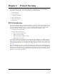
Chapter 2 Product Overview This introduction presents general information about the PC/104 architecture and the CoreModule 745 Single Board Computer (SBC). After reading this chapter you should understand: • PC/104 architecture • Product description • CoreModule 745 features • Major components (ICs) • Headers and Connectors • Specifications PC/104 Architecture The PC/104 architecture affords a great deal of flexibility in system design.
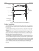
Chapter 2 Product Overview Screws (4) PC/104 Module 0.6 inch Spacers (4) PC/104-Plus Module ISA Bus Expansion Stackthrough Connectors PCI Stackthrough Connectors 0.6 inch Spacers (4) CoreModule 745 CM745stackthru PCI Stackthrough Connectors 0.6 inch Spacers (4) Nuts (4) or Chassis Standoffs Figure 2-1.
Chapter 2 Product Overview Module Features • • • • • • • • CPU Provides an Intel Atom 1.67GHz N455 or 1.83GHz D525 processor core DMI (Direct Media Interface) with 1 GB/s of bandwidth in each direction Enhanced SpeedStep® technology On die 512-kB, 8-way L2 cache Memory Single standard 204-pin DDR3 SODIMM socket Supports +1.
Chapter 2 • • • • 6 Product Overview Ethernet Interface Provides one fully independent Ethernet port Provides integrated LEDs (Link/Activity and Speed) Provides one Intel 82574IT controller chips Provides header for LAN LED signals (gigabit only) Supports IEEE 802.
Chapter 2 Product Overview Block Diagram Figure 2-2 shows the functional components of the CoreModule 745. CPU Intel Atom 1.67GHz VGA N455 or 1.
Chapter 2 Product Overview Major Component (ICs) Definitions Table 2-1 lists the major ICs, including a brief description of each, on the CoreModule 745. Figures 2-3 and 2-4 show the locations of the major ICs. Table 2-1. Major Component Descriptions and Functions 8 Chip Type Mfg. Model Description Function CPU (U1) Intel Atom N455 or D525 1.67GHz or 1.
Chapter 2 Product Overview Table 2-1.
Chapter 2 Product Overview Key: U11 - RS-232 Transceiver (COM1 and COM2) U12 - RS-422/485 Transceiver (COM1 and COM2) U17 - CPLD (Complex Programmable Logic Device) U32 - SPI Flash U38 - RS-232 Transceiver (COM3) U12 U11 U38 U17 CM745_Bottom_Comp_b U32 Figure 2-4. Component Locations (Bottom Side) Header, Connector, and Socket Definitions Table 2-2 describes the headers and connectors of the CoreModule 745 shown in Figure 2-6. Table 2-2.
Chapter 2 Product Overview Table 2-2. Module Header, Connector, and Socket Descriptions (Continued) J7 – Power Top 10-pin, 0.100" (2.54mm), right-angle, shrouded header used for external power connection J8 – SATA0 Top 7-pin, 0.050" (1.27mm) standard connector used for SATA devices J9 – SATA1 Top 7-pin, 0.050" (1.27mm) standard connector used for SATA devices J10 – Ethernet Top 10-pin, 0.079" (2mm) shrouded header used for Gigabit Ethernet signals J11 – Ethernet LED Top 4-pin, 0.049" (1.
Chapter 2 Product Overview J19 J5 J4 J3 JP3 JP4 J22 J23 JP2 J15 BA CD DCBA J14 CM745_Top_Conn_b J24 J2 J1 J20 Key: J1 - PC/104 Plus J2 - PC/104 J3 - Serial COM1 J4 - Serial COM2 J5 - Serial COM3 J6 - Battery J7 - Power J8 - SATA0 J9 - SATA1 J10 - Gigabit Ethernet J11 - Gigabit Ethernet LED J12 - Not supported (On bottom side) J14 - Do Not Populate J15 - Keyboard and Mouse J16 - USB0 and USB1 J17 - USB2 and USB3 J18 - GPIO J19 - Video (LVDS and VGA) J20 - SMBus J22 - Fan J23 - Utility J24 - DD
Chapter 2 Product Overview Jumper Header Definitions Table 2-3 describes the jumper headers shown in Figure 2-7. All jumper headers provide 0.079" (2mm) pitch. Table 2-3. Jumper Settings Jumper Header Installed Removed/Installed JP2 – LVDS Voltage Selection Enable +3.
Chapter 2 Product Overview Specifications Physical Specifications Table 2-4 provides the physical dimensions of the CoreModule 745. Table 2-4. Weight and Footprint Dimensions 14 NOTE Item Dimension Weight 0.12 kg (0.25 lbs) Height (overall) 11.05 mm (0.435 inches) Board thickness 2.362 mm (0.093 inches) Width 96.01 mm (3.78 inches) Length 115.57 mm (4.
Chapter 2 Product Overview 0.33 (8.26mm) 0.20 (5.09mm) 0.00 1.66 (42.04mm) 3.78 (95.89mm) 3.58 (90.81mm) 3.45 (87.63mm) Mechanical Specifications 4.05 (102.87mm) 3.55 (90.17mm) 3.55 (90.17mm) 3.35 (85.09mm) 3.25 (82.55mm) CM745_Top_Dmn_b 2.06 (52.45mm) 0.35 (8.89mm) 0.00 0.20 (5.08mm) 0.00 0.50 (12.70mm) 0.50 (12.7mm) Figure 2-8. Mechanical Overview (Top Side) NOTE CoreModule 745 All dimensions are given in inches. Pin 1 is shown as a black square on headers and connectors.
Chapter 2 Product Overview Power Specifications Table 2-5 provides the power requirements for the CoreModule 745. Table 2-5. Power Supply Requirements Parameter 1.67GHz N455 Characteristics 1.83GHz D525 Characteristics Input Type Regulated DC voltages Regulated DC voltages Typical In-rush Current (Peak) 8.00A (40.00W) 8.00A (40.00W) Typical Idle Current 1.59A (7.96W) 2.20A (10.98W) BIT Current 2.76A (13.82W) 3.73A (18.
Chapter 2 Product Overview Table 2-7. ADLINK Optional Cooling Solutions Cooling Solution Description Passive Heatsink - Copper (without fan) Qualified to maintain optimal performance between -40°C and +85°C. CPU throttles to 1000MHz. (Note: The D525 CPU is qualified only for -20°C to +70°C with a copper heatsink.) Passive Heatsink - Aluminum (without fan) Qualified to maintain optimal performance between -20°C and +70°C. Airflow requirement: 2 m/s.
Chapter 2 Product Overview Figure 2-10. Airflow Requirements NOTE 18 Airflow directions are from Top to Bottom.
Chapter 3 Hardware Overview This chapter discusses the chips and connectors of the module features in the following order: • CPU • Graphics • Memory • Interrupt Channel Assignments • Memory Map • I/O Address Map • Serial Port Interfaces • USB Interfaces • Keyboard and Mouse Interface • Ethernet Interface • Video Interface VGA LVDS • Power Interface • GPIO Interface • Utility Interface Power Button Reset Switch Speaker • SMBus Interface • System Fan Interfa
Chapter 3 Hardware NOTE ADLINK Technology, Inc. only supports the features/options tested and listed in this manual. The main chips used in the CoreModule 745 may provide more features or options than are listed for the CoreModule 745, but some of these features/options are not supported on the module and will not function as specified in the chip documentation. The pin-out tables only of non-standard headers and connectors are included in this chapter.
Chapter 3 Hardware Interrupt Channel Assignments The interrupt channel assignments are shown in Table 3-1. Table 3-1. Interrupt Channel Assignments Device vs IRQ No.
Chapter 3 Hardware I/O Address Map Table 3-3 shows the I/O address map. These are DOS-level addresses. The OS typically hides these physical addresses by way of memory management. Table 3-3.
Chapter 3 Hardware Serial Interfaces The CoreModule 745 provides three serial ports: two RS-232/485/422 ports (COM1 and COM2) and one RS-232 port (COM3). The SCH3114I-NU SIO contains the circuitry for all three serial ports and delivers the signals through three transceivers. The two RS-232/485/422 ports require two transceivers: one ADM213EARSZ (U11) for RS-232 signals and one LTC1334CG (U12) for RS-485/422 signals. The third serial port requires only one ADM213EARSZ transceiver (U38) for RS-232 signals.
Chapter 3 Hardware Table 3-4 defines the pins and corresponding signals for serial ports 1 and 2 headers (J3 and J4), which each consist of 10 pins, 2 rows, odd/even sequence (1, 2), and 0.079" (2mm) pitch. Table 3-4. Serial Ports 1 & 2 Interface Pin Signal Descriptions (J3 and J4) Pin # Signal DB9 # Description 1 DCD* 1 Data Carrier Detect – Indicates external serial device is detecting a carrier signal (i.e., a communication channel is currently open).
Chapter 3 Hardware Table 3-5 describes the pin signals of the serial port 3 header, which consists of 10 pins, two rows, odd/even (1, 2) pin sequence, and 0.079" (2mm) pitch. Table 3-5. Serial Port 3 Interface Pin Signal Descriptions (J5) Pin # Signal DB9 # Description 1 DCD* 1 Data Carrier Detect – Indicates external serial device is detecting a carrier signal (i.e., a communication channel is currently open).
Chapter 3 Hardware Table 3-6. USB0 and USB1 Interface Pin Signals (J16) (Continued) 4 CONN_USB1_N USB1 Port Data Negative 5 CONN_USB0_P USB0 Port Data Positive 6 CONN_USB1_P USB1 Port Data Positive 7 USB_GND0 USB0 Ground 8 USB_GND1 USB1 Ground 9 USB_GND0 USB0 Ground 10 USB_GND1 USB1 Ground Note: The shaded table cells denote power or ground.
Chapter 3 Hardware Table 3-8. Keyboard/Mouse Interface Pin/Signal Definitions (J15) (Continued) 9 CON CLK MOUSE Mouse clock 10 KEY GND Keyboard ground Note: The shaded table cells denote power or ground. Ethernet Interface The CoreModule 745 supports one Gigabit Ethernet interface. The Ethernet interface is implemented from the 82574IT Ethernet controller and provides one GLAN interface, which occupies PCI Express port 2.
Chapter 3 Hardware Video (VGA/LVDS) Interface The CPU provides the graphics control and video signals to the traditional glass CRT monitors and LCD flat panel displays.
Chapter 3 Hardware Table 3-10. Video Interface Pin Signals (J19) (Continued) Pin # Signal Description 28 GND VGA VGA Ground 29 CRT_VSYNC Vertical Sync – Digital Vertical Sync Output to the CRT 30 VCC_CON_DAC +5V Power and Ground for Digital to Analog Converter Note: The shaded table cells denote power or ground. Power Interface The CoreModule 745 requires one +5 volt DC power source and provides a shrouded 10-pin, right-angle header with 2 rows, odd/even pin sequence (1, 2), and 0.100" (2.
Chapter 3 Hardware User GPIO Interface The CoreModule 745 provides GPIO pins for customer use, routing the signals from the ICH8-M chipset to the J18 header. An example test application and source code reside in each BSP directory of the CoreModule 745 Support Software QuickDrive. For instructions on using the example applications, refer to the GPIO Readme in each BSP directory of the QuickDrive. For more information about the GPIO pin operation, refer to the ICH8-M datasheet at: http://www.intel.
Chapter 3 Hardware Table 3-13 describes the pin signals of the Utility interface, which uses a 5-pin, single-row header with 0.100" (2.54mm) pitch. Table 3-13. Utility Interface Pin Signals (J23) Pin # Signal Description 1 /PWR_BTN* External Power Button (Pins 1-2) 2 GND Ground 3 /RESET SW* External Reset Switch signal (Pins 2-3) 4 5V +5 Volts Power 5 SPKR_CONN Speaker Output (Pins 4-5) Note: The shaded table cells denote power or ground. The * symbol indicates the signal is Active Low.
Chapter 3 Hardware Battery Table 3-17 lists the pin signals of the External Battery Input header for backup CMOS RAM and RTC (Real Time Clock), which uses 2 pins, single row, with 0.049" (1.25mm) pitch. Table 3-17. External Battery Input Header (J6) Pin # Signal Description 1 VBAT_EXT +3.0 volts DC 2 GND Ground Note: The shaded table cells denote power or ground.
Chapter 3 Hardware Oops! Jumper (BIOS Recovery) The Oops! jumper function is provided in the event the BIOS settings you have selected prevent you from booting the system. By using the Oops! jumper you can prevent the current BIOS settings in flash from being loaded, allowing you to boot using default settings. Use a jumper to connect the DTR pin (4) to the RI pin (9) on Serial Port 1 (COM 1) prior to boot up to prevent the present BIOS settings from loading.
Chapter 3 Hardware Watchdog Timer The Watchdog Timer (WDT) restarts the system if a mishap occurs, ensuring proper start-up after the interruption. Possible problems include failure to boot properly, the application software’s loss of control, failure of an interface device, unexpected conditions on the bus, or other hardware or software malfunctions. The WDT (Watchdog Timer) can be used both during the boot process and during normal system operation.
Chapter 4 BIOS Setup Introduction This section assumes the user is familiar with general BIOS Setup. Refer to the appropriate PC reference manuals for information about the on-board ROM-BIOS software interface. If ADLINK has added to or modified the standard functions, these functions will be described. Entering BIOS Setup (Local Video Display) To enter BIOS Setup using a local video display for the CoreModule 745: 1. Turn on the display and the power supply to the CoreModule 745. 2.
Chapter 4 9. BIOS Setup Press the F4 key to enter Setup (early in the boot sequence if Quick Boot is set to [Enabled].) If Quick Boot is set to [Enabled], you may never see the screen prompt. 10. Use the key to select the screen menus listed in the Opening BIOS screen. NOTE The serial console port is not hardware protected. Diagnostic software that probes hardware addresses may cause a loss or failure of the serial console functions.
Chapter 4 BIOS Setup BIOS Setup Menus This section provides illustrations of the six main setup screens in the CoreModule 745 BIOS Setup Utility. Below each illustration is a bullet list of the screen’s submenus and setting selections. The setting selections are presented in brackets after each submenu or menu item and the optimal default settings are presented in bold. For more detailed definitions of the BIOS settings, refer to the AMIBIOS8 manual: http://www.ami.com/support/doc/MAN-EZP-80.pdf.
Chapter 4 BIOS Setup BIOS Advanced Setup Screen BIOS Setup Utility Main Advanced Power Boot Security Advanced Settings Exit Configure CPU CPU Configuration Chipset Configuration Video Function Configuration IDE Configuration Super IO Configuration USB Configuration PCI PnP Configuration Remote Access Configuration Watchdog Timer Configuration Enter F1 F10 ESC Select Screen Select Item Go to Sub Screen General Help Save and Exit Exit CM745_BIOS_Advanced_a VXX.
Chapter 4 • BIOS Setup South Bridge Chipset Configuration • SMBUS Controller [Enabled; Disabled] • Onboard Ethernet Controller [Enabled; Disabled] Video Function Configuration Initiate Graphic Adapter [PCI/IGD; IGD] Internal Graphics Mode Select [Enabled, 8MB] DVMT Mode Select [DVMT Mode; Fixed Mode] • • • DVMT/Fixed Memory [128MB; 256MB; Maximum DVMT] Boot Display Device [CRT; LVDS; CRT + LVDS] Flat Panel Type [640x480; 800x600; 1024x768; 1280x800; 1366x768] Spread Spectr
Chapter 4 BIOS Setup Serial Port3 Address [Disabled; 3F8; 2F8; 3E8; 2E8; 2F0; 2E0] • • • • USB Configuration Module Version - X.XX.X - XX.X USB Devices Enabled: None USB Functions [Disabled; USB Port 0; USB Ports 0-1; USB Ports 0-2; USB Ports 0-3] USB 2.0 Controller [Enabled] Legacy USB Support [Disabled; Enabled; Auto] USB 2.
Chapter 4 BIOS Setup • Set GPO1 State [High; Low] • Set GPO2 State [High; Low] • Set GPO3 State [High; Low] • Set GPO4 State [High; Low] GPIs state monitoring • Current GPI1 State High • Current GPI2 State High • Current GPI3 State High • Current GPI4 State High BIOS Power Management Setup Screen BIOS Setup Utility Main Advanced Power Boot Security Exit Power Management Settings Section for Advanced ACPI Configuration ACPI Configuration Hardware Health Configuration + F1 F10 ESC
Chapter 4 BIOS Setup BIOS Boot Setup Screen BIOS Setup Utility Main Advanced Power Boot Security Exit Boot Settings Configure Settings during System Boot Boot Settings Configuration 1st Boot Device 2nd Boot Device 3rd Boot Device 4th Boot Device 5th Boot Device Hard Disk Drives Removable Drives CD/DVD Drives USB Drives Network Drives [Removable Dev] [CD/DVD] [SATA: SM-XGB NANDrive] [USB] [Network] Onboard Lan Boot ROM [Disabled] Enter F1 F10 ESC Select Screen Select Item Go to Sub screen Gene
Chapter 4 BIOS Setup Removable Drives • 1st Drive [Not Installed] CD/DVD Drives • 1st Drive [Not Installed] USB Drives • 1st Drive [Not Installed] Network drives • 1st Drive [Not Installed] Onboard Lan Boot ROM [Disabled; Enabled] BIOS Security Setup Screen Main Advanced Power BIOS Setup Utility Boot Security Exit Security Settings Install or change the password Supervisor Password: Not installed User Password: Not installed Change Supervisor Password Change User Password En
Chapter 4 BIOS Setup BIOS Exit Setup Screen Main Advanced Power BIOS Setup Utility Boot Security Exit Exit Options Exit System Setup after saving the changes. Save Changes and Exit Discard Changes and Exit Discard Changes F10 key can be used for this operation Load Optimal Defaults Load Failsafe Defaults Select Screen Select Item Enter Go to Sub Screen F1 General Help F10 Save and Exit ESC Exit VXX.XX (C) Copyright 1985-20XX, American Megatrends, Inc. CM745_BIOS_Exit_a Figure 4-6.
Appendix A Technical Support ADLINK Technology, Inc. provides a number of methods for contacting Technical Support listed below in Table A-1. Requests for support through the Ask an Expert are given the highest priority, and usually will be addressed within one working day. • ADLINK’s Ask an Expert – This is a comprehensive support center designed to meet all your technical needs. This service is free and available 24 hours a day through the ADLINK web page at http://www.adlinktech.com/AAE/.
Appendix A Technical Support Table A-1. Technical Support Contact Information (Continued) ADLINK Technology Beijing Address: ࣫ҀᏖ⍋⎔ऎϞഄϰ䏃 1 োⲜ߯ࡼॺ E ᑻ 801 ᅸ(100085) Rm. 801, Power Creative E, No. 1, Shang Di East Rd., Beijing, 100085 China Tel: +86-10-5885-8666 Fax: +86-10-5885-8626 Email: market@adlinktech.com ADLINK Technology Shenzhen Address: ⏅ഇᏖफቅऎ⾥ᡔುफऎ催ᮄफϗ䘧 ᭄ᄫᡔᴃು A1 ᷟ 2 ὐ C ऎ (518057) 2F, C Block, Bldg. A1, Cyber-Tech Zone, Gao Xin Ave. Sec. 7, High-Tech Industrial Park S.
Appendix A Technical Support Table A-1. Technical Support Contact Information (Continued) ADLINK Technology, Inc. (Israeli Liaison Office) Address: 6 Hasadna St., Kfar Saba 44424, Israel Tel: +972-9-7446541 Fax: +972-9-7446542 Email: israel@adlinktech.
Appendix A 48 Technical Support Reference Manual CoreModule 745
Index A H Advanced setup screen ....................................... 38 AMI BIOS ...................................................... 1, 37 Atom datasheet reference .......................................... 1 N400, D400/D500 CPUs ................................ 4 N400/D500 series CPU ................................. 20 headers, connectors, and sockets .........................10 heatsink ................................................................17 height ....................................
Index serial connectors ..................................................... 24 ports connector pin outs ................................... 24 Remote Access .............................................. 33 BIOS setup .............................................. 35 site preparation .................................................... 16 SMBus ................................................................ 31 speaker ................................................................