
Instruction Manual
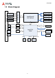
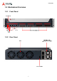
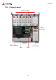
Table Of Contents
- CSA-5200
- Revision History
- Table of Contents
- 1 Overview
- 2 Specifications
- 3 Getting Started
- 4 System Interfaces
- 4.1 Front Panel I/O
- 4.2 Board Layout
- 4.3 Connectors and Jumpers
- 4.3.1 PCIe x4 Connector (PCIE1)
- 4.3.2 CFast Connector (CN17)
- 4.3.3 VGA Header (CNX1)
- 4.3.4 ATX12V Connector (CN24)
- 4.3.5 Fan Connectors (FAN1/FAN6-9)
- 4.3.6 ATX Connector (CN19)
- 4.3.7 mSATA Connectors (CN9/CN48)
- 4.3.8 SATA Connectors (CN30-33)
- 4.3.9 SATADOM Power Connector (CN18, Wafer 1.25mm pitch)
- Clear CMOS Jumper (JBAT1)
- 4.3.11 NIM Slot connectors (PCI1-4)
- 5 LAN Bypass Function
- 6 Watchdog Timer Programming
- 7 BIOS Setup
- Safety Instructions
- Consignes de Sécurité Importantes
- Getting Service

10
CSA-5200
1.5 Package Contents
Before opening, please check the shipping carton for any damage. If the shipping carton and
contents are damaged, notify the dealer for a replacement. Retain the shipping carton and
packing material for inspection by the dealer. Obtain authorization before returning any
product to ADLINK.
Check that the following items are included in the package. If there are any missing items,
contact your dealer:
CSA-5200 Rackmount Network Appliance
VGA cable (pin header to DB-15)
Remote console cable (RJ-45 to DB-9)
Accessory pack (drive bracket mounting hardware)
Power cord
ADLINK All-In-One CD