
Instruction Manual
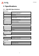
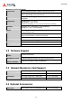
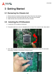
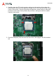
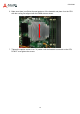
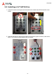
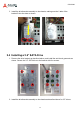
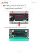
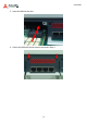
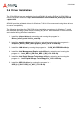
Table Of Contents
- CSA-5200
- Revision History
- Table of Contents
- 1 Overview
- 2 Specifications
- 3 Getting Started
- 4 System Interfaces
- 4.1 Front Panel I/O
- 4.2 Board Layout
- 4.3 Connectors and Jumpers
- 4.3.1 PCIe x4 Connector (PCIE1)
- 4.3.2 CFast Connector (CN17)
- 4.3.3 VGA Header (CNX1)
- 4.3.4 ATX12V Connector (CN24)
- 4.3.5 Fan Connectors (FAN1/FAN6-9)
- 4.3.6 ATX Connector (CN19)
- 4.3.7 mSATA Connectors (CN9/CN48)
- 4.3.8 SATA Connectors (CN30-33)
- 4.3.9 SATADOM Power Connector (CN18, Wafer 1.25mm pitch)
- Clear CMOS Jumper (JBAT1)
- 4.3.11 NIM Slot connectors (PCI1-4)
- 5 LAN Bypass Function
- 6 Watchdog Timer Programming
- 7 BIOS Setup
- Safety Instructions
- Consignes de Sécurité Importantes
- Getting Service
11
CSA-5200
2 Specifications
2.1 CSA-5200 Specifications
Main System
CPU
Intel® Xeon® E3-1275 v3 (4C/8T)
Intel® Xeon® E3-1225 v3 (4C/4T)
Intel® Core™ i3-4330 (2C/4T)
L2 Cache
8MB/8MB/4MB
Chipset
Intel® C226 PCH
Memory
Four DDR3-1066/1333/1600 * 240-Pin Long-DIMM sockets, non-
ECC, up to 32 GB
BIOS
AMI BIOS on SPI flash memory
Operating Systems
Windows 7 64bit, Linux kernel 2.6 and above
(default: no OS installed)
Power Supply
300W AC 1+1 redundant (hot-swappable)
I/O Interfaces - Front
NIM Slots
4x Network Interface Module (NIM) slots
Ethernet
2x RJ-45 10/100/1000BASE-T Ethernet port
Remote Console
1x RJ-45 serial port
USB
2x USB 3.0
I/O Interfaces - Onboard
Security Acceleration
1x PCIe x4 Gen2 socket for acceleration card
Graphics
1x VGA header onboard
Storage
Drive Bays
4x 2.5” or 3.5” SATA drive bays
Other
1x SATADOM*, 1x CFast socket
*Note: *SATADOM shares SATA port with drive bays.
Buttons/LEDs
Power
1x ATX power button, rocker type (rear)
Bypass
1x bypass button (front)
LEDs
Power, Bypass Status, Drive Activity