
Instruction Manual
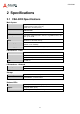
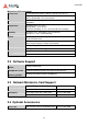
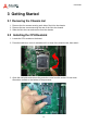
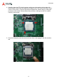
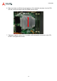
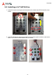
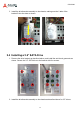
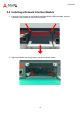
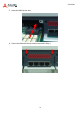
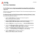
Table Of Contents
- CSA-5200
- Revision History
- Table of Contents
- 1 Overview
- 2 Specifications
- 3 Getting Started
- 4 System Interfaces
- 4.1 Front Panel I/O
- 4.2 Board Layout
- 4.3 Connectors and Jumpers
- 4.3.1 PCIe x4 Connector (PCIE1)
- 4.3.2 CFast Connector (CN17)
- 4.3.3 VGA Header (CNX1)
- 4.3.4 ATX12V Connector (CN24)
- 4.3.5 Fan Connectors (FAN1/FAN6-9)
- 4.3.6 ATX Connector (CN19)
- 4.3.7 mSATA Connectors (CN9/CN48)
- 4.3.8 SATA Connectors (CN30-33)
- 4.3.9 SATADOM Power Connector (CN18, Wafer 1.25mm pitch)
- Clear CMOS Jumper (JBAT1)
- 4.3.11 NIM Slot connectors (PCI1-4)
- 5 LAN Bypass Function
- 6 Watchdog Timer Programming
- 7 BIOS Setup
- Safety Instructions
- Consignes de Sécurité Importantes
- Getting Service
13
CSA-5200
3 Getting Started
3.1 Removing the Chassis Lid
1. Remove the four screws securing each side of the lid to the chassis.
2. Remove the two screws securing the rear of the lid to the chassis.
3. Slide the lid to the rear and remove from the chassis.
3.2 Installing the CPU/Heatsink
1. Locate the CPU sockets on the board.
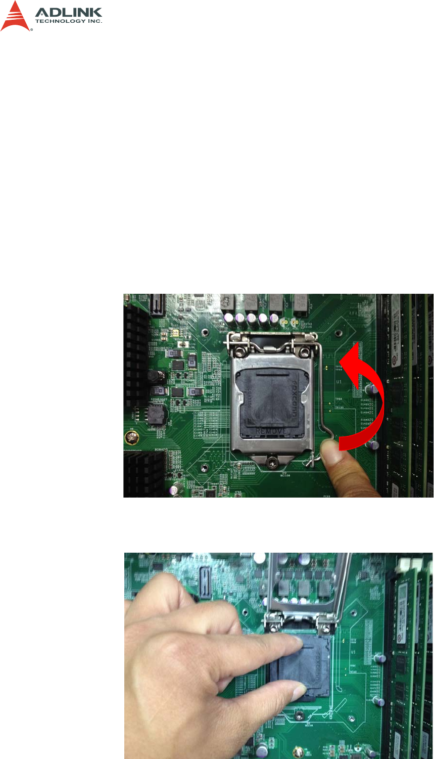
2. Press the load lever, move it outwards until it is clear of the retention tab, then raise it
3. Open the load plate and remove the protective cover from the socket. Do not touch
the socket contacts or the bottom of the processor.