
Instruction Manual
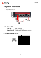
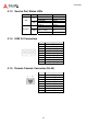
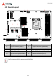
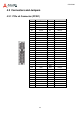
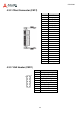
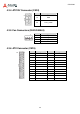
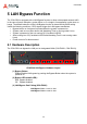
Table Of Contents
- CSA-5200
- Revision History
- Table of Contents
- 1 Overview
- 2 Specifications
- 3 Getting Started
- 4 System Interfaces
- 4.1 Front Panel I/O
- 4.2 Board Layout
- 4.3 Connectors and Jumpers
- 4.3.1 PCIe x4 Connector (PCIE1)
- 4.3.2 CFast Connector (CN17)
- 4.3.3 VGA Header (CNX1)
- 4.3.4 ATX12V Connector (CN24)
- 4.3.5 Fan Connectors (FAN1/FAN6-9)
- 4.3.6 ATX Connector (CN19)
- 4.3.7 mSATA Connectors (CN9/CN48)
- 4.3.8 SATA Connectors (CN30-33)
- 4.3.9 SATADOM Power Connector (CN18, Wafer 1.25mm pitch)
- Clear CMOS Jumper (JBAT1)
- 4.3.11 NIM Slot connectors (PCI1-4)
- 5 LAN Bypass Function
- 6 Watchdog Timer Programming
- 7 BIOS Setup
- Safety Instructions
- Consignes de Sécurité Importantes
- Getting Service
21
CSA-5200
4 System Interfaces
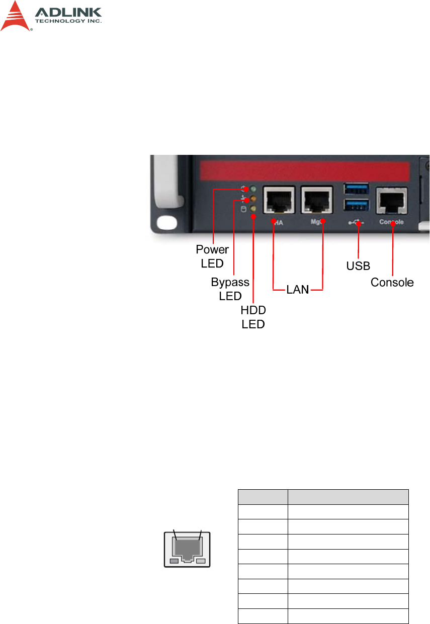
4.1 Front Panel I/O
4.1.1 Status LEDs
Power LED Green: Power On
Bypass Status LED Red: Bypass; Off: No Bypass
HDD Activity LED Flashing Yellow: Read/Write; Off: No activity
4.1.2 LAN Connector (RJ-45)
Pin Signal
1 MID0+
2 MID0-
3 MID1+
4 MID2+
5 MID2-
6 MID1-
7 MID3+
8 MID3-
8
1
Right
LED
Left
LED