
Instruction Manual
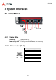
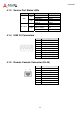
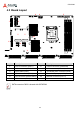
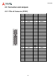
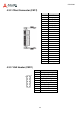
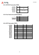
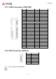
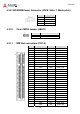
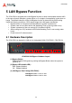
Table Of Contents
- CSA-5200
- Revision History
- Table of Contents
- 1 Overview
- 2 Specifications
- 3 Getting Started
- 4 System Interfaces
- 4.1 Front Panel I/O
- 4.2 Board Layout
- 4.3 Connectors and Jumpers
- 4.3.1 PCIe x4 Connector (PCIE1)
- 4.3.2 CFast Connector (CN17)
- 4.3.3 VGA Header (CNX1)
- 4.3.4 ATX12V Connector (CN24)
- 4.3.5 Fan Connectors (FAN1/FAN6-9)
- 4.3.6 ATX Connector (CN19)
- 4.3.7 mSATA Connectors (CN9/CN48)
- 4.3.8 SATA Connectors (CN30-33)
- 4.3.9 SATADOM Power Connector (CN18, Wafer 1.25mm pitch)
- Clear CMOS Jumper (JBAT1)
- 4.3.11 NIM Slot connectors (PCI1-4)
- 5 LAN Bypass Function
- 6 Watchdog Timer Programming
- 7 BIOS Setup
- Safety Instructions
- Consignes de Sécurité Importantes
- Getting Service
25
CSA-5200
4.3.2 CFast Connector (CN17)
Pin Signal
S1 GND
S2 CF_TX_DP
S3 CF_TX_DN
S4 GND
S5 CF_RX_DN
S6 CF_RX_DP
S7 GND
P1 CFast_CDI
P2 GND
P3 NC
P4 NC
P5 NC
P6 NC
P7 NC
P8 GND
P9 NC
P10 NC
P11 NC
P12 NC
P13 P3V3
P14 P3V3
P15 GND
P16 GND
P17 CFast_CDO
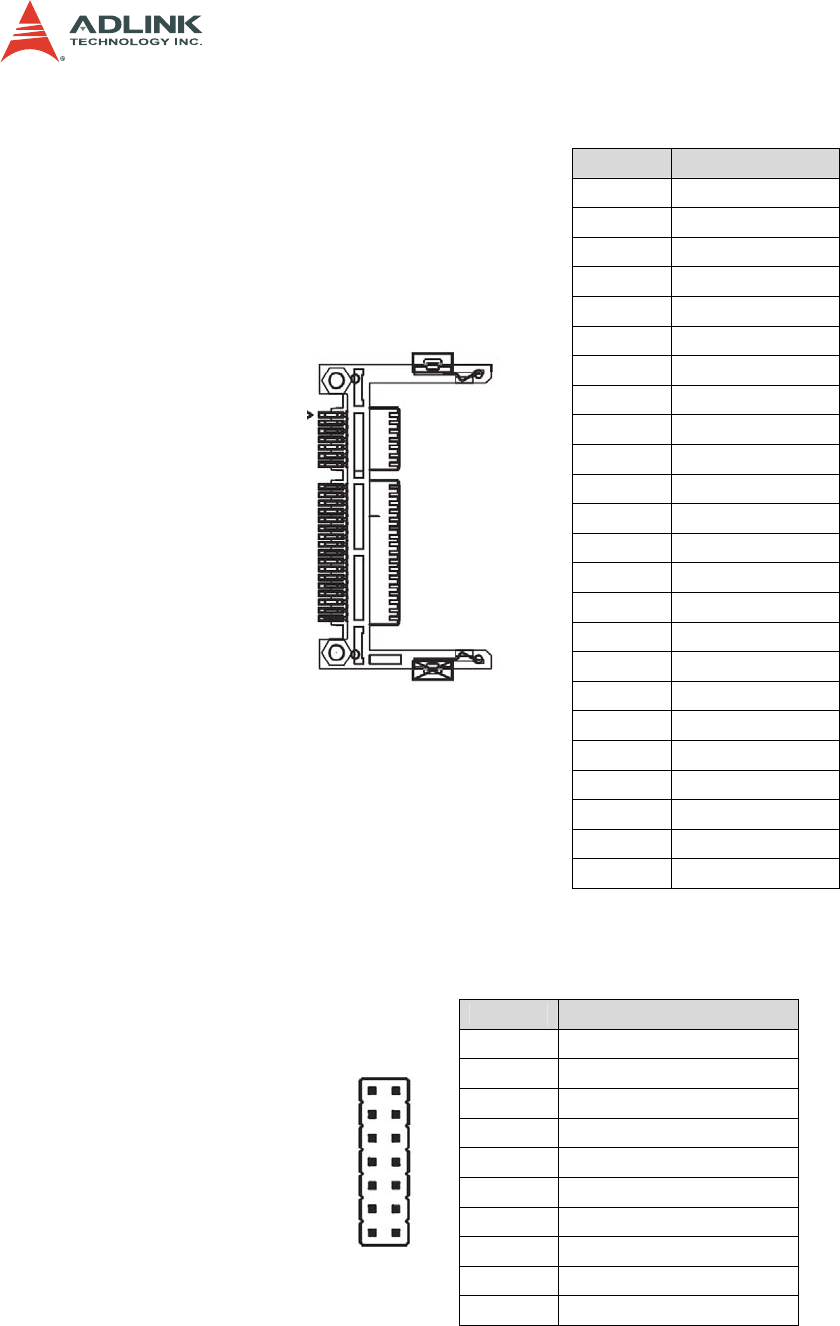
4.3.3 VGA Header (CNX1)
Pin Signal
1 S_DDC_DATA_R
2 S_DDC_CLK_R
3 S_VGA_RED_CONN
4 S_VGA_GREEN_CONN
5 S_VGA_BLUE_CONN
6 S_VGA_HSYNC
7 S_VGA_VSYNC
8 VGA_VCC
9 NC
10-14 GND
1
2