
Instruction Manual
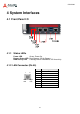
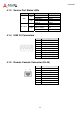
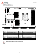
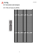
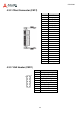
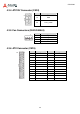
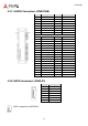
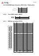
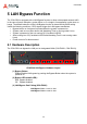
Table Of Contents
- CSA-5200
- Revision History
- Table of Contents
- 1 Overview
- 2 Specifications
- 3 Getting Started
- 4 System Interfaces
- 4.1 Front Panel I/O
- 4.2 Board Layout
- 4.3 Connectors and Jumpers
- 4.3.1 PCIe x4 Connector (PCIE1)
- 4.3.2 CFast Connector (CN17)
- 4.3.3 VGA Header (CNX1)
- 4.3.4 ATX12V Connector (CN24)
- 4.3.5 Fan Connectors (FAN1/FAN6-9)
- 4.3.6 ATX Connector (CN19)
- 4.3.7 mSATA Connectors (CN9/CN48)
- 4.3.8 SATA Connectors (CN30-33)
- 4.3.9 SATADOM Power Connector (CN18, Wafer 1.25mm pitch)
- Clear CMOS Jumper (JBAT1)
- 4.3.11 NIM Slot connectors (PCI1-4)
- 5 LAN Bypass Function
- 6 Watchdog Timer Programming
- 7 BIOS Setup
- Safety Instructions
- Consignes de Sécurité Importantes
- Getting Service
27
CSA-5200
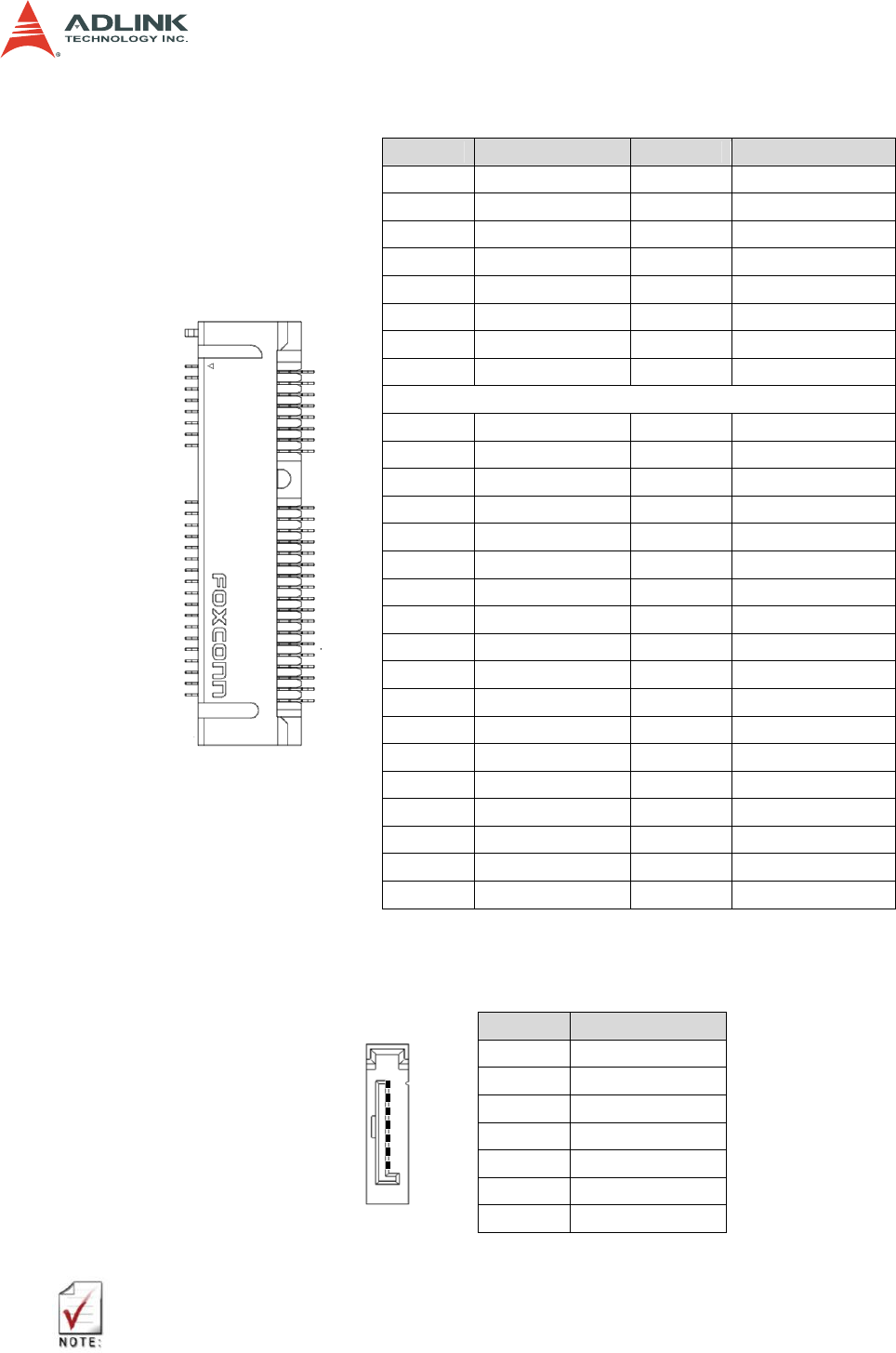
4.3.7 mSATA Connectors (CN9/CN48)
Pin Signal Pin Signal
1 NC 2 P3V3
3 NC 4 GND
5 NC 6 P1V5
7 NC 8 NC
9 GND 10 NC
11 NC 12 NC
13 NC 14 NC
15 GND 16 NC
17 NC 18 GND
19 NC 20 NC
21 NC 22 NC
23 RXP0_R 24 P3V3
25 RXN0_R 26 GND
27 GND 28 P1V5
29 GND 30 NC
31 TXN0_R 32 NC
33 TXP0_R 34 GND
35 GND 36 NC
37 GND 38 NC
39 P3V3 40 GND
41 P3V3 42 NC
43 NC 44 NC
45 NC 46 NC
47 NC 48 P1V5
49 NC 50 GND
51 NC 52 P3V3
4.3.8 SATA Connectors (CN30-33)
Pin Signal
1 Ground
2 TXP
3 TXN
4 Ground
5 RXN
6 RXP
7 Ground
CN32 is shared with SATADOM.
1
1
1
2