
Instruction Manual
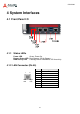
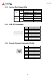
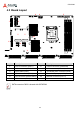
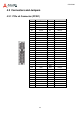
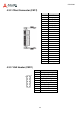
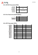
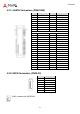
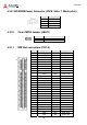
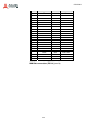
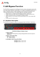
Table Of Contents
- CSA-5200
- Revision History
- Table of Contents
- 1 Overview
- 2 Specifications
- 3 Getting Started
- 4 System Interfaces
- 4.1 Front Panel I/O
- 4.2 Board Layout
- 4.3 Connectors and Jumpers
- 4.3.1 PCIe x4 Connector (PCIE1)
- 4.3.2 CFast Connector (CN17)
- 4.3.3 VGA Header (CNX1)
- 4.3.4 ATX12V Connector (CN24)
- 4.3.5 Fan Connectors (FAN1/FAN6-9)
- 4.3.6 ATX Connector (CN19)
- 4.3.7 mSATA Connectors (CN9/CN48)
- 4.3.8 SATA Connectors (CN30-33)
- 4.3.9 SATADOM Power Connector (CN18, Wafer 1.25mm pitch)
- Clear CMOS Jumper (JBAT1)
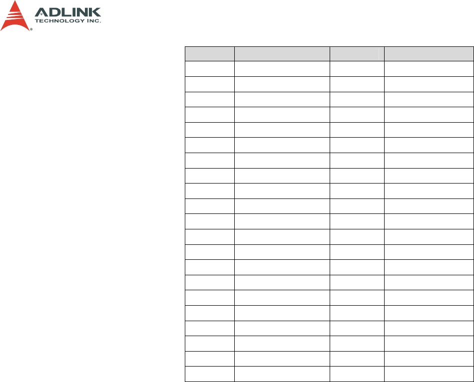
- 4.3.11 NIM Slot connectors (PCI1-4)
- 5 LAN Bypass Function
- 6 Watchdog Timer Programming
- 7 BIOS Setup
- Safety Instructions
- Consignes de Sécurité Importantes
- Getting Service
29
CSA-5200
Pin Signal Pin Signal
A29
PCIE-RXP3 B29 GND
A30
PCIE-RXN3 B30 NC
A31
GND B31 NC
A32
NC B32 GND
A33
NC B33 PCIE-TXP4
A34
GND B34 PCIE-TXN4
A35
PCIE-RXP4 B35 GND
A36
PCIE-RXN4 B36 GND
A37
GND B37 PCIE-TXP5
A38
GND B38 PCIE-TXN5
A39
PCIE-RXP5 B39 GND
A40
PCIE-RXN5 B40 GND
A41
GND B41 PCIE-TXP6
A42
GND B42 PCIE-TXN6
A43
PCIE-RXP6 B43 GND
A44
PCIE-RXN6 B44 GND
A45
GND B45 PCIE-TXP7
A46
GND B46 PCIE-TXN7
A47
PCIE-RXP7 B47 GND
A48
PCIE-RXN7 B48 NC
A49
GND B49 GND
NIM Slot connectors (PCI1-4) (con'td)