
Instruction Manual
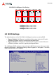
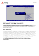
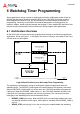
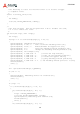
Table Of Contents
- CSA-5200
- Revision History
- Table of Contents
- 1 Overview
- 2 Specifications
- 3 Getting Started
- 4 System Interfaces
- 4.1 Front Panel I/O
- 4.2 Board Layout
- 4.3 Connectors and Jumpers
- 4.3.1 PCIe x4 Connector (PCIE1)
- 4.3.2 CFast Connector (CN17)
- 4.3.3 VGA Header (CNX1)
- 4.3.4 ATX12V Connector (CN24)
- 4.3.5 Fan Connectors (FAN1/FAN6-9)
- 4.3.6 ATX Connector (CN19)
- 4.3.7 mSATA Connectors (CN9/CN48)
- 4.3.8 SATA Connectors (CN30-33)
- 4.3.9 SATADOM Power Connector (CN18, Wafer 1.25mm pitch)
- Clear CMOS Jumper (JBAT1)
- 4.3.11 NIM Slot connectors (PCI1-4)
- 5 LAN Bypass Function
- 6 Watchdog Timer Programming
- 7 BIOS Setup
- Safety Instructions
- Consignes de Sécurité Importantes
- Getting Service
31
CSA-5200
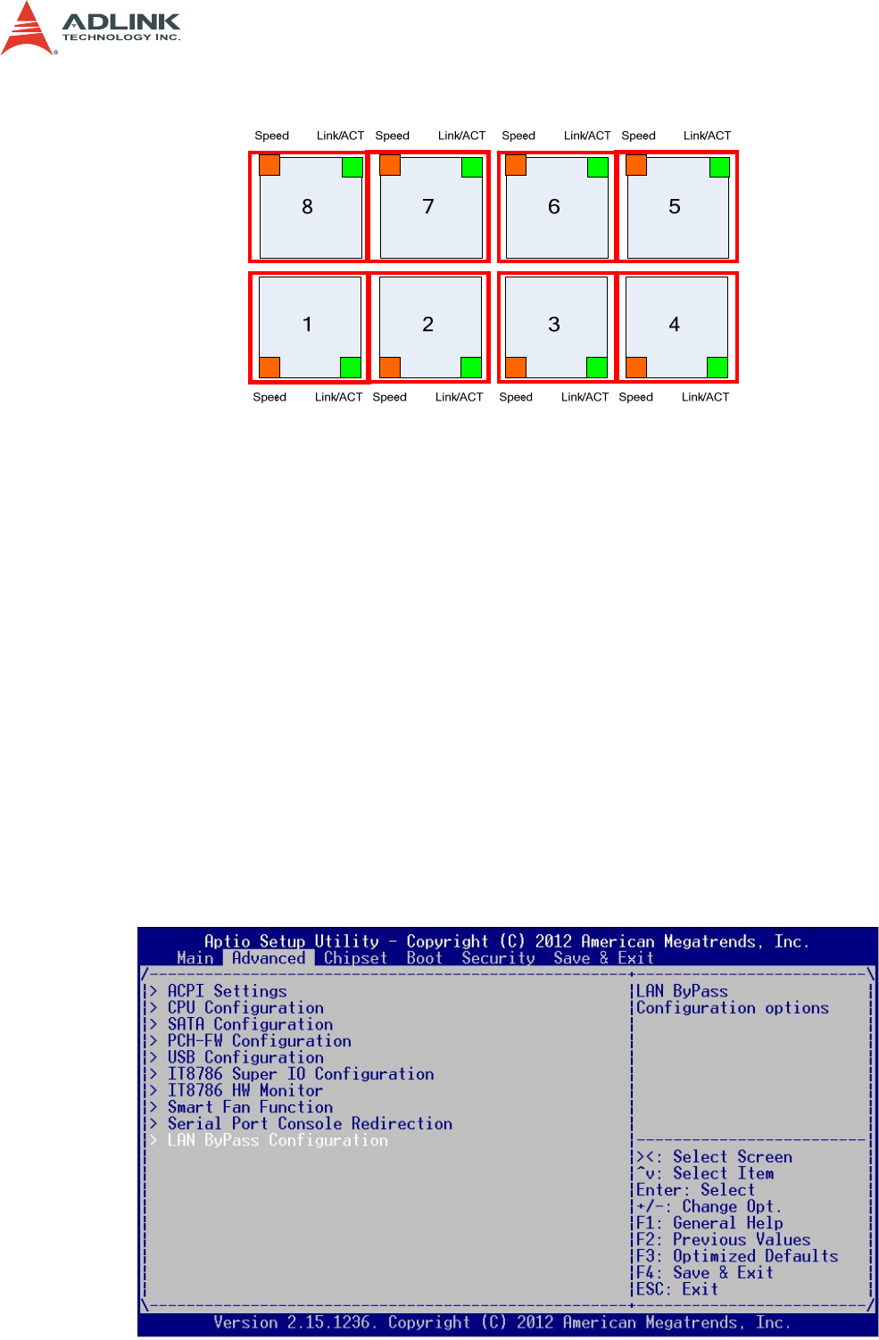
CSA-Z8X10 LAN Bypass Port Pairing
LAN Bypass Pair 1: LAN1 & LAN2
LAN Bypass Pair 2: LAN3 & LAN4
LAN Bypass Pair 3: LAN5 & LAN6
LAN Bypass Pair 4: LAN7 & LAN8
5.2 BIOS Settings
The default behaviour of the CSA-5200's LAN Bypass function is set in the BIOS.
• Bypass Enabled: LAN Bypass is enabled until the system boots into OS and is
disabled by software control or by pushing the Bypass Button.
• Bypass Disabled: LAN Bypass is disabled until the system boots into OS and is
enabled by software control or by pushing the Bypass Button.
The LAN Bypass BIOS setting is set by entering the BIOS setup menu: Advanced > LAN
Bypass Configuration > LAN Bypass Setting, choose "Bypass" or "No Bypass". The BIOS
factory default setting is "No Bypass".