
Instruction Manual
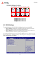
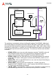
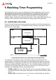
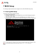
Table Of Contents
- CSA-5200
- Revision History
- Table of Contents
- 1 Overview
- 2 Specifications
- 3 Getting Started
- 4 System Interfaces
- 4.1 Front Panel I/O
- 4.2 Board Layout
- 4.3 Connectors and Jumpers
- 4.3.1 PCIe x4 Connector (PCIE1)
- 4.3.2 CFast Connector (CN17)
- 4.3.3 VGA Header (CNX1)
- 4.3.4 ATX12V Connector (CN24)
- 4.3.5 Fan Connectors (FAN1/FAN6-9)
- 4.3.6 ATX Connector (CN19)
- 4.3.7 mSATA Connectors (CN9/CN48)
- 4.3.8 SATA Connectors (CN30-33)
- 4.3.9 SATADOM Power Connector (CN18, Wafer 1.25mm pitch)
- Clear CMOS Jumper (JBAT1)
- 4.3.11 NIM Slot connectors (PCI1-4)
- 5 LAN Bypass Function
- 6 Watchdog Timer Programming
- 7 BIOS Setup
- Safety Instructions
- Consignes de Sécurité Importantes
- Getting Service

40
CSA-5200
7 BIOS Setup
The following chapter describes basic navigation for the CSA-5200 BIOS setup utility.
7.1 Entering BIOS Setup
To enter the setup screen, follow these steps:
1. Power on the motherboard
2. Press the < Delete > key on your keyboard when you see the following text prompt: <
Press DEL to enter Setup >
3. After you press the < Delete > key, the main BIOS setup menu displays. You can
access the other setup screens from the main BIOS setup menu, such as Chipset and
Power menus.
In most cases, the < Delete > key is used to invoke the setup screen. However, there
are several cases that use other keys, such as < F1 >, < F2 >, and so on.