
Instruction Manual
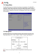
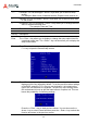
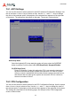
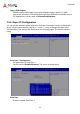
Table Of Contents
- CSA-5200
- Revision History
- Table of Contents
- 1 Overview
- 2 Specifications
- 3 Getting Started
- 4 System Interfaces
- 4.1 Front Panel I/O
- 4.2 Board Layout
- 4.3 Connectors and Jumpers
- 4.3.1 PCIe x4 Connector (PCIE1)
- 4.3.2 CFast Connector (CN17)
- 4.3.3 VGA Header (CNX1)
- 4.3.4 ATX12V Connector (CN24)
- 4.3.5 Fan Connectors (FAN1/FAN6-9)
- 4.3.6 ATX Connector (CN19)
- 4.3.7 mSATA Connectors (CN9/CN48)
- 4.3.8 SATA Connectors (CN30-33)
- 4.3.9 SATADOM Power Connector (CN18, Wafer 1.25mm pitch)
- Clear CMOS Jumper (JBAT1)
- 4.3.11 NIM Slot connectors (PCI1-4)
- 5 LAN Bypass Function
- 6 Watchdog Timer Programming
- 7 BIOS Setup
- Safety Instructions
- Consignes de Sécurité Importantes
- Getting Service
41
CSA-5200
7.2 Setup Menu
The Main BIOS setup menu is the first screen that you can navigate to. The Main BIOS
setup menu screen has two main frames. The left frame displays all the options that can be
configured. “Grayed” options cannot be configured, and “Blue” options can be. The right
frame displays the key legend. Above the key legend is an area reserved for a text message.
When an option is selected in the left frame, it is highlighted in white. Often a text message
will accompany it.
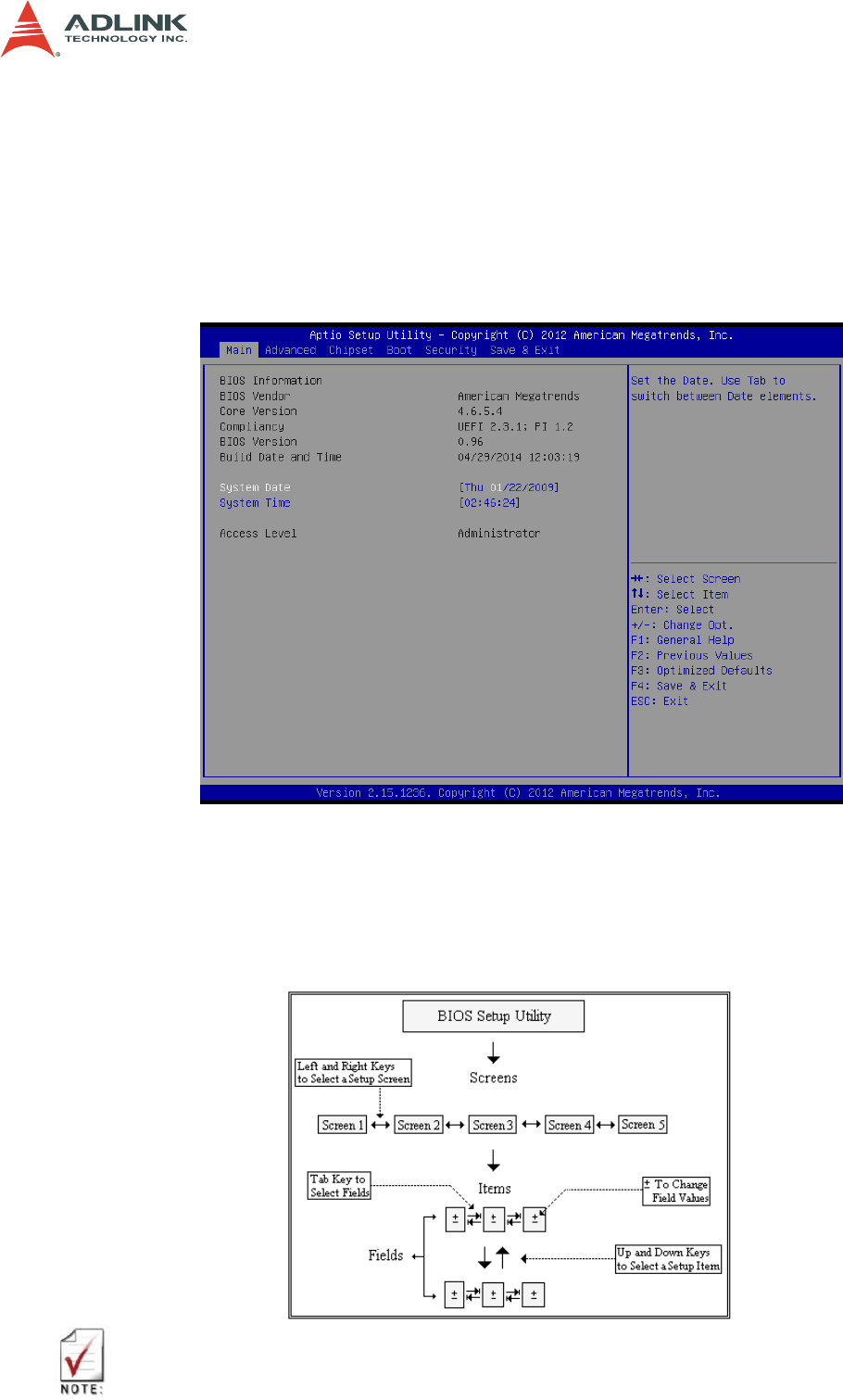
7.3 Navigation
The BIOS setup/utility uses a key-based navigation system called hot keys. Most of the
BIOS setup utility hot keys can be used at any time during the setup navigation process.
These keys include < F1 >, < F10 >, < Enter >, < ESC >, < Arrow > keys, and so on.
There is a hot key legend located in the right frame on most setup screens.