
Instruction Manual
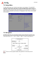
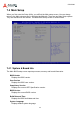
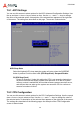
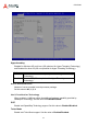
Table Of Contents
- CSA-5200
- Revision History
- Table of Contents
- 1 Overview
- 2 Specifications
- 3 Getting Started
- 4 System Interfaces
- 4.1 Front Panel I/O
- 4.2 Board Layout
- 4.3 Connectors and Jumpers
- 4.3.1 PCIe x4 Connector (PCIE1)
- 4.3.2 CFast Connector (CN17)
- 4.3.3 VGA Header (CNX1)
- 4.3.4 ATX12V Connector (CN24)
- 4.3.5 Fan Connectors (FAN1/FAN6-9)
- 4.3.6 ATX Connector (CN19)
- 4.3.7 mSATA Connectors (CN9/CN48)
- 4.3.8 SATA Connectors (CN30-33)
- 4.3.9 SATADOM Power Connector (CN18, Wafer 1.25mm pitch)
- Clear CMOS Jumper (JBAT1)
- 4.3.11 NIM Slot connectors (PCI1-4)
- 5 LAN Bypass Function
- 6 Watchdog Timer Programming
- 7 BIOS Setup
- Safety Instructions
- Consignes de Sécurité Importantes
- Getting Service
44
CSA-5200
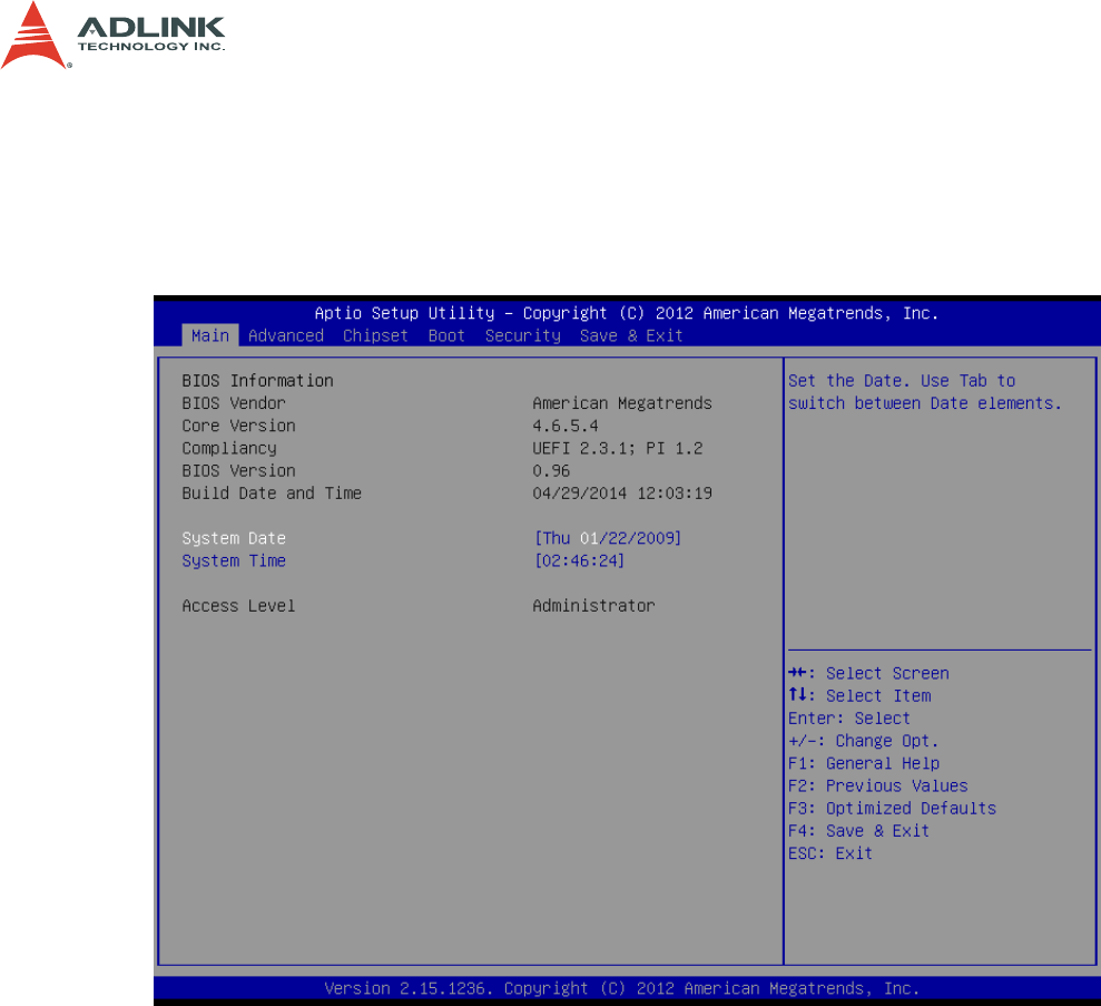
7.4 Main Setup
When you first enter the Setup Utility, you will find the Main setup screen. You can always
return to the Main setup screen by selecting the Main tab. There are two Main Setup options.
They are described in this section. The Main BIOS Setup screen is shown below.
7.4.1 System & Board Info
The Main BIOS setup screen reports processor, memory and board information.
BIOS Vendor
Displays the BIOS vendor.
Core Version
Displays the BIOS core version.
Compliancy Version
Displays the current UEFI Specification version.
BIOS Version
Displays the current BIOS version.
Build Data and Time
Displays the BIOS build data and time.
System Language
Displays default system language.