
Instruction Manual
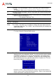
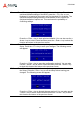
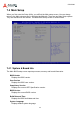
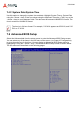
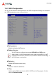
Table Of Contents
- CSA-5200
- Revision History
- Table of Contents
- 1 Overview
- 2 Specifications
- 3 Getting Started
- 4 System Interfaces
- 4.1 Front Panel I/O
- 4.2 Board Layout
- 4.3 Connectors and Jumpers
- 4.3.1 PCIe x4 Connector (PCIE1)
- 4.3.2 CFast Connector (CN17)
- 4.3.3 VGA Header (CNX1)
- 4.3.4 ATX12V Connector (CN24)
- 4.3.5 Fan Connectors (FAN1/FAN6-9)
- 4.3.6 ATX Connector (CN19)
- 4.3.7 mSATA Connectors (CN9/CN48)
- 4.3.8 SATA Connectors (CN30-33)
- 4.3.9 SATADOM Power Connector (CN18, Wafer 1.25mm pitch)
- Clear CMOS Jumper (JBAT1)
- 4.3.11 NIM Slot connectors (PCI1-4)
- 5 LAN Bypass Function
- 6 Watchdog Timer Programming
- 7 BIOS Setup
- Safety Instructions
- Consignes de Sécurité Importantes
- Getting Service
48
CSA-5200
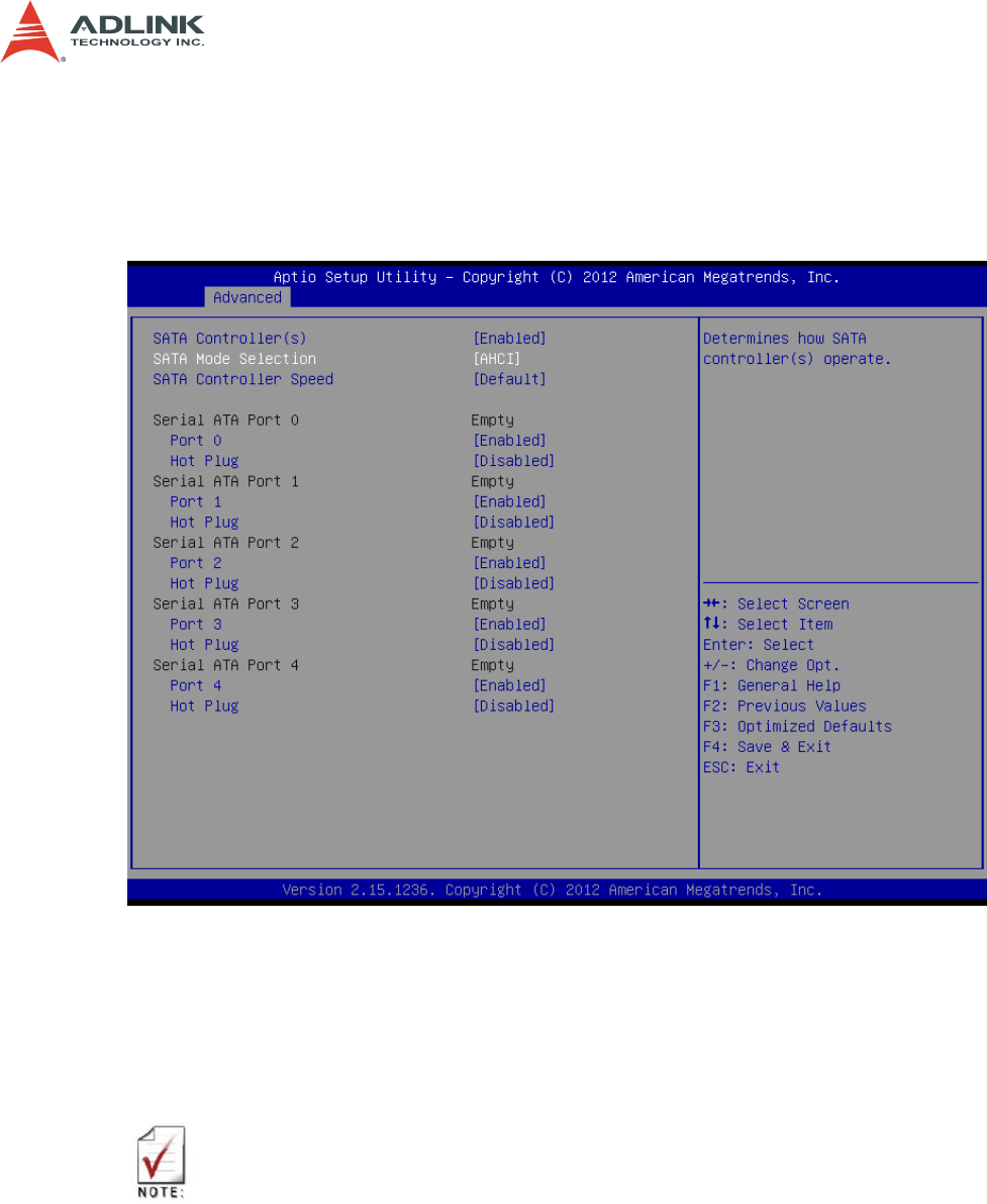
7.5.3 SATA Configuration
You can use this screen to select options for the SATA Configuration Settings. An example of
the SATA Configuration screen is shown below.
SATA Controller(s)
Enables or disables SATA device.
SATA Mode Selection
The SATA can be configured as a legacy IDE, AHCI and RAID mode.
When system is in RAID mode and the user needs to setup BIOS, do NOT
push the NumLock button, otherwise, it is possible to make the BIOS hang. If
the BIOS hangs, reset system.
SATA Port 0-4
Displays SATA device name string.
Port 0-4
Enable or disable the SATA Port.
Hot Plug
Appears when SATA mode is set to AHCI. SATA Ports Hot Plug support. Set this
value to Enabled/Disabled.