
Instruction Manual
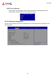
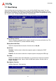
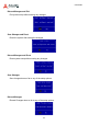
Table Of Contents
- CSA-5200
- Revision History
- Table of Contents
- 1 Overview
- 2 Specifications
- 3 Getting Started
- 4 System Interfaces
- 4.1 Front Panel I/O
- 4.2 Board Layout
- 4.3 Connectors and Jumpers
- 4.3.1 PCIe x4 Connector (PCIE1)
- 4.3.2 CFast Connector (CN17)
- 4.3.3 VGA Header (CNX1)
- 4.3.4 ATX12V Connector (CN24)
- 4.3.5 Fan Connectors (FAN1/FAN6-9)
- 4.3.6 ATX Connector (CN19)
- 4.3.7 mSATA Connectors (CN9/CN48)
- 4.3.8 SATA Connectors (CN30-33)
- 4.3.9 SATADOM Power Connector (CN18, Wafer 1.25mm pitch)
- Clear CMOS Jumper (JBAT1)
- 4.3.11 NIM Slot connectors (PCI1-4)
- 5 LAN Bypass Function
- 6 Watchdog Timer Programming
- 7 BIOS Setup
- Safety Instructions
- Consignes de Sécurité Importantes
- Getting Service
61
CSA-5200
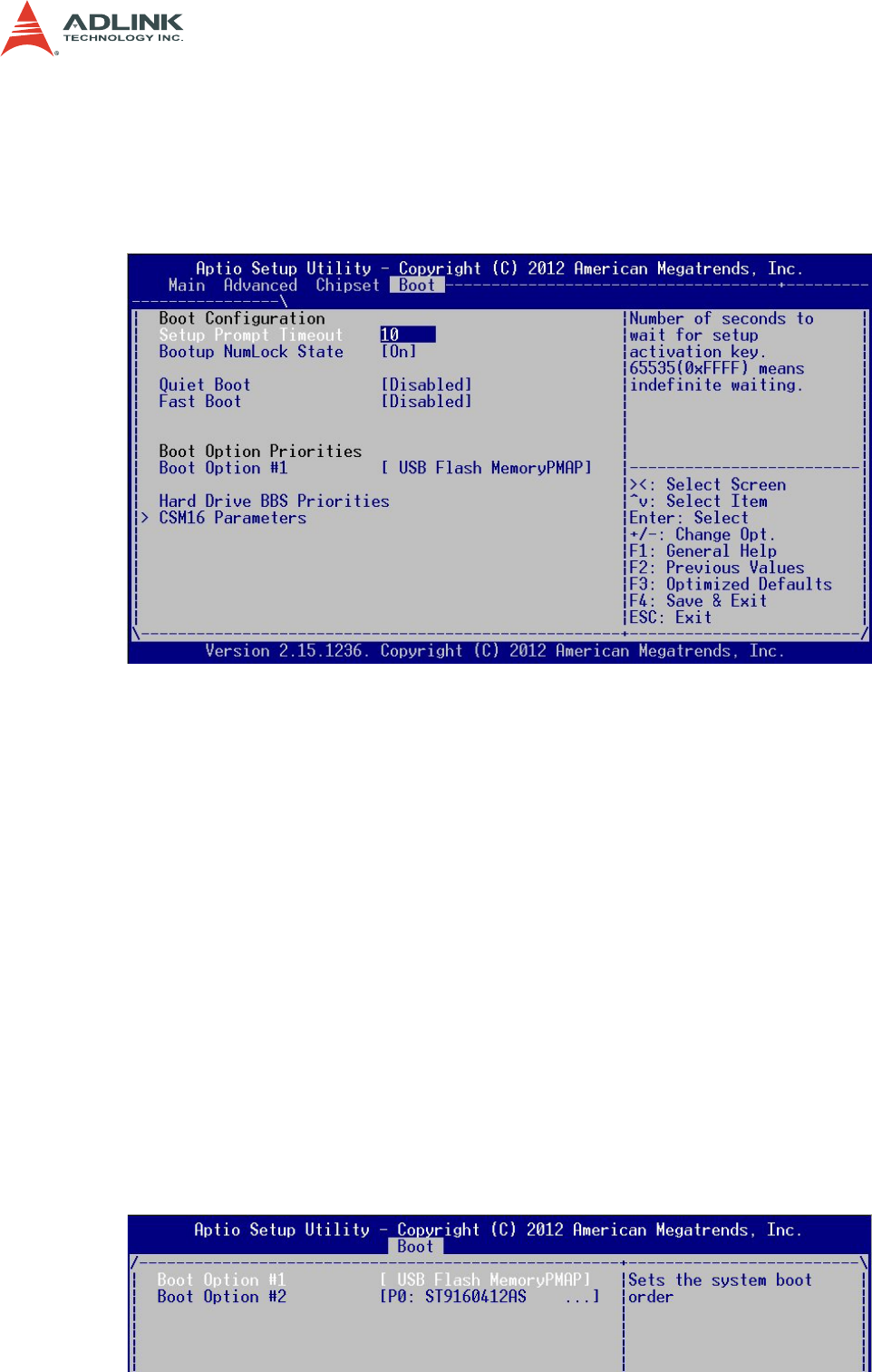
7.7 Boot Setup
Select the Boot tab from the setup screen to enter the Boot BIOS Setup screen. You can
select any of the items in the left frame of the screen, such as Boot Device Priority, to go to
the sub menu for that item. You can display a Boot BIOS Setup option by highlighting it using
the < Arrow > keys. The Boot Settings screen is shown below:
Setup Prompt Timeout
Set the number of seconds that the system will wait for the setup activation key. The
number of 65535(0xFFFF) means indefinite waiting.
Bootup NumLOck State
Select the keyboard NumLock state. Set this value to On, Off.
Quiet Boot
Disabled - Set this value to allow the computer system to display the POST
messages.
Enabled - Set this value to allow the computer system to display the OEM logo.
Fast Boot
Enables or disables boot with initialization of a minimal set of devices required to
launch active boot option. Has no effect for BBS boot options. Set this value to
Enable / Disable.
Boot Option Priorities
Set Boot Option #1 -2 boot priority.