
Instruction Manual
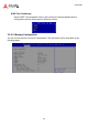
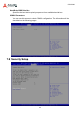
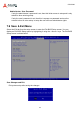
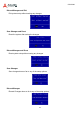
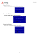
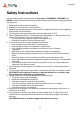
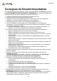
Table Of Contents
- CSA-5200
- Revision History
- Table of Contents
- 1 Overview
- 2 Specifications
- 3 Getting Started
- 4 System Interfaces
- 4.1 Front Panel I/O
- 4.2 Board Layout
- 4.3 Connectors and Jumpers
- 4.3.1 PCIe x4 Connector (PCIE1)
- 4.3.2 CFast Connector (CN17)
- 4.3.3 VGA Header (CNX1)
- 4.3.4 ATX12V Connector (CN24)
- 4.3.5 Fan Connectors (FAN1/FAN6-9)
- 4.3.6 ATX Connector (CN19)
- 4.3.7 mSATA Connectors (CN9/CN48)
- 4.3.8 SATA Connectors (CN30-33)
- 4.3.9 SATADOM Power Connector (CN18, Wafer 1.25mm pitch)
- Clear CMOS Jumper (JBAT1)
- 4.3.11 NIM Slot connectors (PCI1-4)
- 5 LAN Bypass Function
- 6 Watchdog Timer Programming
- 7 BIOS Setup
- Safety Instructions
- Consignes de Sécurité Importantes
- Getting Service
63
CSA-5200
Administrator / User Password
If only the administrator’s password is set, then this limits access to setup and is only
asked for when entering setup.
If only the user’s password is set, then this is a power on password and must be
entered to boot or enter setup. In setup the user will have administrator rights.
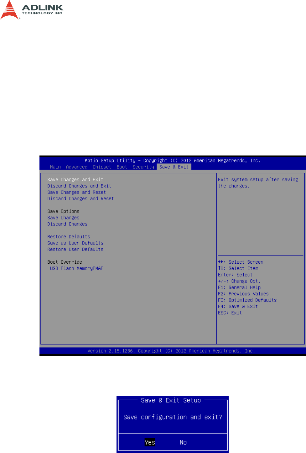
7.9 Save & Exit Menu
Select the Exit tab from the setup screen to enter the Exit BIOS Setup screen. You can
display an Exit BIOS Setup option by highlighting it using the < Arrow > keys. The Exit BIOS
Setup screen is shown below.
Save Changes and Exit
Exit system setup after saving the changes.