EXP-ISO-COM8 EPIC ExpressTM Add-on-Board Technical Manual TME-EXP-ISO-COM8-R1V0 Revision 1.0 / February 14 ©LiPPERT Adlink Technology GmbH Hans-Thoma-Str. 11 D-68163 Mannheim http://www.adlinktech.
Technical Manual EXP-ISO-COM8 LiPPERT Document: TME-EXP-ISO-COM8-R1V0 Revision 1.0 Copyright © 2009 LiPPERT Adlink Technology GmbH, All rights reserved Contents and specifications within this manual are subject of change without notice. Trademarks Windows XP is a trademark of Microsoft Corporation. EPIC Express is a registered trademark of PC/104 Consortium. All other trademarks appearing in this document are the property of their respective owners.
Table of Contents 1 1.1 Overview 1 Introduction ................................................................................................................................. 1 Features .................................................................................................................................................................... 1 Block Diagram ..........................................................................................................................................
2 2.1 Module Description 15 OXPCIe958 ................................................................................................................................. 15 Serial Ports ............................................................................................................................................................ 15 DSUB-9 Connectors ...........................................................................................................................................
Acronyms CTS Clear To Send DCD Data Carrier Detect DSR Data Set Ready DTR Data Terminal Ready FIFO First In First Out GND Ground ISO-GND Isolated Ground MSI-Extend Message Signaled Interrupts - Extend PCB Printed Circuit Board PCI Peripheral Component Interconnect PCIe Peripheral Component Interconnect Express RI Ring Indicator RTS Request To Send RxD Received Data SerDes Serializer/Deserializer TxD Transmitted Data USB Universal Serial Bus TME-EXP-ISO-COM8-R1V0 Rev 1.
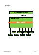
1 Overview 1.1 Introduction The EXP-ISO-COM8 is an Add-on Module conforming to the EPIC Express Specification. It comprises eight independent serial ports with RS232 / RS422 / RS485 standards. Especially for the embedded market all interfaces are galvanic isolated that external distortions cannot damage the whole Module as well as the CPU board. The galvanic isolation is a good solution for potential differences with interconnections. The EXP-ISO-COM8 supports Stack-up and Stack-down to a CPU Module.
Block Diagram TME-EXP-ISO-COM8-R1V0 Rev 1.
1.2 Ordering Information EXP-ISO-COM8 Models Order number Description 714-0002-10 EXP-ISO-COM8 with galvanic isolated serial ports Commercial operating temp. range: 0°C…+60°C 814-0002-10 EXP-ISO-COM8 with galvanic isolated serial ports Industrial operating temp. range: -20°C…+60°C 914-0002-10 EXP-ISO-COM8 with galvanic isolated serial ports Extended operating temp. range: -40°C…+85°C Cable Sets and Accessories There are some options offered for the EXP-ISO-COM8.
1.3 Specifications Electrical Specifications Supply voltage +5 V DC Rise time < 10 ms Supply voltage tolerance ± 5% * Supply current maximal 0,5 A (with transfer on all 8 ports at the same time) typical 0,4 A (with transfer on 4 ports at the same time) minimal 0,36 A (with no transfer) Environmental Specifications Operating: Temperature range 0 … 60 °C (commercial version) -20 … 60 °C (industrial version) -40 … 85 °C (extended version) Temperature change max.
Mechanical Dimensions (L x W) 165 mm x 115 mm Height max. 17 mm on top side above PCB max. 12 mm on bottom side above PCB Weight 168 g Mounting 4 mounting holes Board-to-Board Stacking 22 mm height Note: It is strongly recommend using plastic spacers instead of metal spacers to mount the board. With metal spacers, there is a possible danger to create a short circuit with the components located around the mounting holes. This can damage the board! TME-EXP-ISO-COM8-R1V0 Rev 1.
Mecchanical viiew Front view Side vview System m stack-up viiew with Hurricane-QM57 aand heat spre eader Note e For detailed d mechanical drawings or step s files plea ase contact ouur support departmentt. TME-EXP-ISO O-COM8-R1V0 0 Rev 1.
Metrics on Top The connectors' pin 1 is marked with an arrow. TME-EXP-ISO-COM8-R1V0 Rev 1.
Getting Started 1.4 Connector Locations Top Port 4 X14 Port 8 Port 3 X6 X15 Port 2 X18 Port 7 X7 Port 6 PC/104 X10 Plus Port 5 X11 Port 1 X19 PCI/104 Express The connectors' pin 1 is marked with an arrow. TME-EXP-ISO-COM8-R1V0 Rev 1.
Bottom PC/104 PCI/104 Plus Express TME-EXP-ISO-COM8-R1V0 Rev 1.
TME-EXP-ISO-COM8-R1V0 Rev 1.
1.5 Jumper Locations Port 4 X12 Port 8 X4 Port 3 X13 Port 7 X5 Port 2 X16 Port 6 X8 Port 1 X17 Port 5 X9 The connectors' pin 1 is marked with an arrow. TME-EXP-ISO-COM8-R1V0 Rev 1.
1.6 LED indicatorrs Onbo oard there is a yellow LED that t shows the w working state of o the OXPCIe e chip. TME-EXP-ISO O-COM8-R1V0 0 Rev 1.
1.7 Hardware Setup Caution Be sure to observe the EMC security measures. Make sure you are always at the same potential as the module. Caution Do never connect or disconnect the EXP-ISO-COM8 Add-on Module with a CPU board while that is running. Be sure that your power supply is able to provide enough current to your system. An insufficient power supply leads to an instable system. The EXP-ISO-COM8 does not need any cooling devices. TME-EXP-ISO-COM8-R1V0 Rev 1.
1.8 Software Setup Driver packages are available for the following operating systems: Linux Windows XP Please contact our support department support@lippertembedded.com or have a look at the website www.lippertmebedded.com for downloading the necessary drivers. Installation guide and all necessary information is provided in the driver package. TME-EXP-ISO-COM8-R1V0 Rev 1.
2 Module Description 2.1 OXPCIe958 The device combines a fully integrated, single-lane PCI Express end-point controller and SerDes with eight high-performance 950 UART. The OXPCIe958 achieves outstanding performance including 128 byte transmit and receive FIFOs of the 950 UART, with advanced system management features such as MSI/MSI-X interrupt handling and bus master DMA to maximize data throughput while substantially reducing CPU and system overheads.
Pin RS232 RS485 Pin RS232 RS485 1 DCD Not used 2 DSR RXD+ 3 RXD RXD- 4 RTS TXD+ 5 TXD TXD- 6 CTS Not used 7 DTR Not used 8 RI Not used 9 ISOGND ISOGND 10 Not used Not used Pin 1 is marked with a small arrow TME-EXP-ISO-COM8-R1V0 Rev 1.
RS48 85-Selection n and Termin nation Jump pers Conne ector type IDC6 pin hea ader 2.00 mm Use 2 mm jumperss to terminate e lines correcttly. The R RS485 termina ation jumpers are located aat the top of the t printed ciircuit board, ssee chapter 1.5 For se electing the RS485 R mode the pins 5 and d 6 at each po ort have to be e shorted.
2.2 PC/104-Plus Bus Connector The PC/104-plus bus is not used on that module. The mounted connector forward the signal through. Pin A B C D 1 GND n.c. n.c. n.c. 2 n.c. n.c. n.c. n.c. 3 n.c. GND n.c. n.c. 4 n.c. n.c. GND n.c. 5 GND n.c. n.c. GND 6 n.c. n.c. n.c. n.c. 7 n.c. n.c. GND n.c. 8 n.c. n.c. n.c. n.c. 9 n.c. GND n.c. n.c. 10 GND n.c. n.c. n.c. 11 n.c. n.c. n.c. GND 12 n.c. n.c. GND n.c. 13 n.c. GND n.c. n.c. 14 GND n.c. n.c.
Pin A B C D 26 n.c. n.c. GND n.c. 27 n.c. n.c. n.c. GND 28 GND n.c. n.c. n.c. 29 n.c. n.c. n.c. n.c. 30 n.c. n.c. n.c. GND TME-EXP-ISO-COM8-R1V0 Rev 1.
2.3 PCI/104 Express Bus Interface The EXP-ISO-COM8 uses x1 link of the PCI/104-Express bus. According to the EPIC Express specification it depends on the stacking position above or below the CPU board which link is used. On the module there is a PCI Express switch that detects the type of connection and forwards the other links according to the specification. Top PCI/104-Express Connector Connector Type: Samtec ASP-142781-05 Signal PIN Signal 1 3 USB OC +3.3V 2 4 PE RST# +3.
The following table shows the shifting of PCI Express links from top to bottom connector. The rest of not listed PCI/104 Express pins are directly forwarded. PCI/104 Express TOP OXPCIe958 3x1 link Bottom - shifted 2x1 link 3x1 link shifted 1x1 link 2x1 link shifted 1x0 link 1x1 link TME-EXP-ISO-COM8-R1V0 Rev 1.
Bottom PCI/104-Express Connector Connector Type: Samtec ASP-129646-03 Signal PIN Signal 1 3 USB OC +3.3V 2 4 PE RST# +3.
TME-EXP-ISO-COM8-R1V0 Rev 1.
2.4 Portt Isolation n Each sserial port is extra isolated. Onboard theere are two quad q channel isolators for o one COM porrt. With the ADuM M5401 and AD DuM5404 from m Analog Devvices the data a channels are e optical und the power su upply is galvan nic isolated. In conclusion there are eigh ht separated zones with th heir own poteential regardin ng to VCC, GND and Data.
Appendix A, Contact Information Headquarters LiPPERT ADLINK Technology GmbH Hans-Thoma-Straße 11 68163 Mannheim Germany Phone +49 621 43214-0 Fax +49 621 4321430 E-mail sales: emea@adlinktech.com Support: helpdesk@adlinktech.com RMA: RMA.EMEA@adlinktech.com Website http://www.adlinktech.com/rugged/index.php TME-EXP-ISO-COM8-R1V0 Rev 1.
Appendix B, Additional Information B.1 Additional Reading Datasheet of the OXPCIe958 at http://www.plxtech.com B.2 PCI/104 ExpressTM A copy of the latest PCI/104 Express and can be obtained from the PC/104 Consortium's website at www.pc104.org TME-EXP-ISO-COM8-R1V0 Rev 1.
Appendix C, Getting Help Should you have technical questions that are not covered by the respective manuals, please contact our support department at http://askanexpert.adlinktech.com . Please allow one working day for an answer. Returning Products for Repair To return a product to ADLINK Technology GmbH for repair, you need to get a Return Material Authorization (RMA) number first. Please print the RMA Request Form from http://www.adlinktech.com/lippert/rma.
Appendix D, Filename Date Revision History Edited Change by TME-EXP-ISO-COM8-R0V0.doc 2009-12-10 CS Draft TME-EXP-ISO-COM8-R0V1.doc 2010-04-12 MF Some minor changes Driver section added TME-EXP-ISO-COM8-R0V2.doc 2011-01-18 MF Some minor changes MTBF value added TME-EXP-ISO-COM8-R0V3.doc 2011-02-21 MF Mechanical dimensions corrected part numbers 8xx, 9xx added Appendix A new US address TME-EXP-ISO-COM8-R1V0.doc 2014-02-03 MF Ch. 1.