
Instruction Manual

3
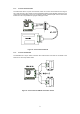
2.4 PC/104-plus configuration
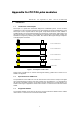
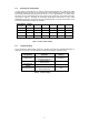
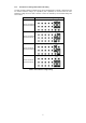
A rotary switch on the PCM-9112+ is used for switching the appropriate CLK, IDSEL, INT, REQ
and GNT signals from the PCI bus. If the PCM-9112+ card is inserted in a position nearest to the
PC/104-plus motherboard, the switch must be set to 0 or 4. For signal stability, the rotary switch
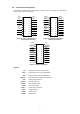
should be set to the appropriate position with respect to the module slot. The module stack order
was shown in Figure 1. According to PC/104-plus specification, module slots 3 and 4 share
REQ2/GNT2, hence they cannot both have bus-mastering devices. In another word, module 3 and
4 cannot be stacked with 2 PCM-9112+ modules.
Rotary Switch
Position
Module
Slot
CLK IDSEL INT REQ GNT
0 or 4 1 CLK0 IDSEL0 INTA REQ0* GNT0*
1 or 5 2 CLK1 IDSEL1 INTB REQ1* GNT1*
2 or 6 3 CLK2 IDSEL2 INTC REQ2* GNT2*
3 or 7 4 CLK3 IDSEL3 INTD REQ2* GNT2*
* Only for Bus Master card
Table 1: Rotary switch setting
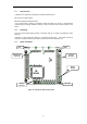
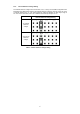
2.5 Jumpers Setting
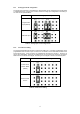
On the PCM-9112+ DAQ module, there are 5 jumpers that need to be adjusted depending on
application requirements. The following table describes the attributes of these jumpers.
Configuration Attributes Jumpers
Analog Inputs
Single-ended or
Differential Analog Input
JP1 and JP4
Clock Source
Internal Clock or
External Clock
JP2
D/A Reference
Voltage
-10V or -5V JP3
D/A Reference Source
Internal Reference or
External Reference
JP5
Table 2: Jumpers setting