PXI-2020/2022 8/16-CH 16-Bit 250 KS/s Simultaneous Sampling Card User’s Manual Manual Rev. 2.01 Revision Date: October 4, 2010 Part No: 50-17032-2010 Advance Technologies; Automate the World.
Copyright 2010 ADLINK TECHNOLOGY INC. All Rights Reserved. The information in this document is subject to change without prior notice in order to improve reliability, design, and function and does not represent a commitment on the part of the manufacturer. In no event will the manufacturer be liable for direct, indirect, special, incidental, or consequential damages arising out of the use or inability to use the product or documentation, even if advised of the possibility of such damages.
Getting Service from ADLINK Contact us should you require any service or assistance. ADLINK Technology, Inc. Address: 9F, No.166 Jian Yi Road, Chungho City, Taipei County 235, Taiwan קᗼխࡉؑ৬ԫሁ 166 ᇆ 9 ᑔ Tel: +886-2-8226-5877 Fax: +886-2-8226-5717 Email: service@adlinktech.com Ampro ADLINK Technology, Inc. Address: 5215 Hellyer Avenue, #110, San Jose, CA 95138, USA Tel: +1-408-360-0200 Toll Free: +1-800-966-5200 (USA only) Fax: +1-408-360-0222 Email: info@adlinktech.com ADLINK Technology (China) Co., Ltd.
ADLINK Technology (Europe) GmbH Address: Nord Carree 3, 40477 Duesseldorf, Germany Tel: +49-211-495-5552 Fax: +49-211-495-5557 Email: emea@adlinktech.com ADLINK Technology, Inc. (French Liaison Office) Address: 15 rue Emile Baudot, 91300 Massy CEDEX, France Tel: +33 (0) 1 60 12 35 66 Fax: +33 (0) 1 60 12 35 66 Email: france@adlinktech.com ADLINK Technology Japan Corporation Address: 151-0072 ᧲੩ㇺᷦ⼱ᐈ䊱⼱㩷 1-1-2 ᦺᣣ↢ᐈ䊱⼱䊎䊦 8F Asahiseimei Hatagaya Bldg.
Table of Contents Table of Contents..................................................................... i List of Tables.......................................................................... iii List of Figures ........................................................................ iv 1 Introduction ........................................................................ 1 1.1 1.2 1.3 1.4 Features............................................................................... Applications ............
4.4 4.5 4.6 4.7 4.8 Timebase Exporting ...................................................... 30 Trigger Sources ................................................................. 31 Software Trigger ........................................................... 31 External Digital Trigger ................................................. 31 PXI Star Trigger ............................................................ 32 PXI Trigger Bus ............................................................
List of Tables Table Table Table Table Table Table Table Table Table Table Table Table Table Table Table Table Table Table Table 1-1: 1-2: 1-3: 1-4: 1-5: 1-6: 1-7: 1-8: 1-9: 2-1: 2-2: 2-3: 2-4: 2-5: 3-1: 3-2: 4-1: 4-2: 4-3: Basic Specifications .................................................. 3 Triggers .................................................................... 4 Digital I/O .................................................................. 5 General Purpose Timer/Counter .....................
List of Figures Figure 2-1: Figure 3-1: Figure 3-2: Figure 4-1: Figure 4-2: Figure 4-3: Figure 4-4: Figure 4-5: Figure 4-6: Figure 4-7: PXI-2020/2022 PCB Layout..................................... 11 Ground-referenced Source and Differential Input.... 21 Floating Source and Differential Input ..................... 22 PXI-2022 Functional Block Diagram........................ 23 PXI-2020/2022 Analog Input Path ........................... 24 Basic Acquisition Timing of PXI-2020/2022.............
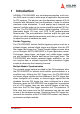
1 Introduction ADLINK's PXI-2020/2022 are simultaneous-sampling multi-function DAQ cards to meet a wide range of application requirements for PXI systems. The devices can simultaneously sample 8/16 AI channels with differential input configurations in order to achieve maximum noise elimination. If more analog input channels are required, multiple cards can be synchronized through the PXI Trigger bus.
Calibration The PXI-2020/2022 includes a precision on-board reference with very low temperature drift. This feature not only provides a stable calibration source for auto-calibration but also maintains stable acquisition accuracy over a wide temperature range. The automated calibration process can be done through software without need for any manually adjustments.
1.2 Applications Automotive Testing Cable Testing Transient signal measurement ATE Laboratory Automation Biotech measurement 1.
Triggers Trigger Specifications Model Name PXI-2020/2022 Trigger Sources (refer to section 4.4 for details) (1)Software (2)AFI [0..7] (3)PXI Star Trigger (4)PXI Trigger Bus[5] (SSI) (5)SMB Trigger I/O (please refer to chapter 2.3 for details) *GA 3-8 can use (1), (2), (4), (5) as output signals. GA2 can use all options.
Digital I/O Digital I/O Specifications Model Name PXI-2020/2022 Number of Channel 4 input/output Compatibility Input 3.3 V or 5 V TTL Output 3.3 V TTL Input Logic Levels Input low voltage: 0.8 V (max) Input high voltage: 2.0 V(min) Output Logic Levels Output low voltage: 0.4 V (max) Output high voltage: 2.
Timebase System Timebase Specifications Model Name PXI-2020/2022 Timebase Source (1) Internal: onboard 80MHz oscillator (2) External from hardware IO Sampling Rate Range Timebase divided by 32-bit counter. TIMEBASE(80MHz) divider to the achieve equivalent sampling rate of DAQ. The equation is: Sampling rate = TIMEBASE / ScanIntrv The value of TIMEBASE depends on the card type.
General General Specifications Model Name PXI-2020/2022 Dimensions Single 3U PXI module, 100mm by 160mm (not including connector) Connector 68-pin VHDCI-type female Operating Environment Ambient temperature: 0 to 55°C Relative humidity: 10% to 90% non-condensing Storage Environment Ambient temperature: -20 to 80°C Relative humidity: 5% to 95% non-condensing Table 1-7: General Power Requirements Power Specifications Model Name PXI-2020/2022 +3.3 V 1.5 A (typical) +5 V 1.
1.4 Performance Analog Input Measurement[1] Model Number PXI-2020/2022 Function Result under 25°C ± 5°C Offset Error (gain = 1) ±0.6 mV (Typical) Gain Error (gain = 1) ±0.02% (Typical) –3dB small signal bandwidth gain = 1 : 1 MHz gain = 4 : 700 KHz System Noise gain = 1 : 0.5 mVrms gain = 4 : 0.
2 Getting Started This chapter describes the proper installation environment, installation procedures, its package contents and basic information user should be aware of. The PXI-2020/2022 performs an automatic configuration of the IRQ, and port address. The PCI_SCAN software utility can be used to read the system configuration. NOTE: Diagrams and images of equipment mentioned are used for reference only. Actual system configuration and specs may vary. 2.
2.2 Package Contents Before continuing, check the package contents for any damage and check if the following items are included in the packaging: PXI-2020/2022 Simultaneous Data Acquisition Card ADLINK All-in-one DVD Software Installation Guide PXI-2020/2022 User’s Manual. Caution Do not install or apply power to equipment that is damaged or if there is missing/incomplete equipment. Retain the shipping carton and packing materials for inspection.
2.3 Mechanical Drawing and I/O Connectors Figure 2-1: PXI-2020/2022 PCB Layout The ADLINK PXI-2020/2022 is packaged in a Euro-card form factor compliant with PXI specifications measuring 160 mm in length and 100 mm in height (not including connectors). The connector types and functions are described as follows.
SMB Connector SMB Connector 1: TRG IO SMB Connector 2: Sync CLK_OUT1 SMB Connector 3: Sync CLK_OUT0 SMB Connector 4: CLK IN Connector Direction Type Description/Function TRG IO Input Output SMB The TRG IO is a bidirectional port for external digital trigger input or output. CLK OUT1 Output SMB The CLK OUTOUT 1 is a 50Ω, DC-coupled output; CLK_OUT0 and CLK_OUT1 is from the same source.
TRG IO, as an Output Port Connector type SMB Compatibility 3.3 V TTL Output low voltage: 0.2 V (max) Output Logic Level Output high voltage: 2.4 V (min) Driving Capability 8 mA Minimum Output Pulse Width 12.5 ns Table 2-3: TRG IO, as an Output Port CLK IN (External Clock from Front Panel) Connector Type SMB Clock Type Sine wave or square wave Input Impedance 50 Ω Input Coupling AC Input Range 1 VP-P to 2 VP-P Overvoltage Protection 2.
2.4 Installing the module To install the PXI-2020/2022 module: 1. Turn off the PXI system/chassis and disconnect the power plug from the power source. 2. Align the module’s edge with the card guide in the PXI chassis. 3. Slide the module into the chassis, until resistance is felt from the PXI connector. 4. Push the ejector upwards and fully insert the module into the chassis. 5. Once inserted, a “click” can be heard from the ejector latch. 6. Tighten the screw on the front panel. 7.
2.5 Software Support ADLINK provides comprehensive software drivers and packages to suit various user approaches to building a system. Aside from programming libraries, such as DLLs, for most Windows-based systems, ADLINK also provides drivers for other application environment such as LabVIEW® and MATLAB®. ADLINK also provides ActiveX component ware for measurement and SCADA/ HMI, and breakthrough proprietary software applications. All software options are included in the ADLINK All-in-One DVD.
2.6 PCI Configuration 1. Plug and Play: As a plug and play component, the card requests an interrupt number via its PCI controller. The system BIOS responds with an interrupt assignment based on the card information and on known system parameters. These system parameters are determined by the installed drivers and the hardware load seen by the system. 2. Configuration: The board configuration is done on a board-by-board basis for all PCI boards on your system.
3 Signal Connections This chapter describes the connectors of the PXI-2020/2022, and the signal connection between the PXI-2020/2022 and external devices. 3.1 Connectors Pin Assignment The PXI-2020/2022 is equipped with one 68-pin VHDCI-type connector (ACL-10568-1). It is used for digital input/output, analog input, and ti-mer/counter signals, etc. The pin assignments of the connectors are de-fined in Table 3-1 and Figure 3-2.
AIL11 14 48 AIH11 AGND 13 47 AGND AIL4 12 46 AIH4 AIL12 11 45 AIH12 AGND 10 44 AGND AIL5 9 43 AIH5 AIL13 8 42 AIH13 AGND 7 41 AGND AIL6 6 40 AIH6 AIL14 5 39 AIH14 AGND 4 38 AGND AIL7 3 37 AIH7 AIL15 2 36 AIH15 AGND 1 35 AGND Table 3-1: PXI-2020/2022 68-pin VHDCI-type Pin Assignment Legend: Pin # Signal Name Reference Direction Description 58, 55, 52, 49, 46, 43, 40,37, 57, 54, 51, 48, 45, 42, 39, 36 AIH <0..15> AIL <0..
Pin # Signal Name Reference Direction Description 64 AFI2 DGND Input Auxiliary Function Input 2 (AD_TRIG_SRC2,AD_TIM ER_SRC2,AD_CONV_SR C2)/(GPTC_CLK0) 63 AFI3 DGND Input Auxiliary Function Input 3 (AD_TRIG_SRC3,AD_TIM ER_SRC3,AD_CONV_SR C3)/(GPTC_GATE0) 28 AFI4 DGND Input Auxiliary Function Input 4 (AD_TRIG_SRC4,AD_TIM ER_SRC4,AD_CLK_SRC4 )/(GPTC_CLK1) 62 AFI5 DGND Input Auxiliary Function Input 5 (AD_TRIG_SRC5,AD_TIM ER_SRC5,AD_CONV_SR C5)/(GPTC_GATE1) 27 AFI6 DGND In-put/Output
3.2 Analog Input Signal Connection The PXI-2020/2022 provides 8/16 differential analog input channels. The analog signal can be converted to digital values by the A/D converter. To avoid ground loops and obtain more accurate measurements from the A/D conversion, it is quite important to understand the signal source type and how to connect the analog input signals. 3.2.
3.2.2 Input Connect Configurations - Differential Input Mode x = 0, ..., 31 AIxH Ground Referenced Signal Source Commonmode noise & Ground potential Input Multiplexer Instrumentation Amplifier + - AIxL + To A/D Converter - Vcm AIGND Figure 3-1: Ground-referenced Source and Differential Input The differential input mode provides two inputs that respond to signal voltage difference between them.
x = 0, ...
4 Function Block and Operation Theory The operation theory of the functions on the PXI-2020/2022 is described in this chapter. The functions include the A/D conversion, Digital I/O and General Purpose Counter/Timer. The operation theory can help you understand how to configure and program the PXI-2020/2022. The entire PXI-2020 series of cards includs the PXI-2020/2022.
4.2 Basic AI Acquisition In this section, the basic acquisition timing is explained. 4.2.1 Analog Input Path The following figure shows the block diagram of the single analog input path of a PXI-2020/2022. Each path provides a choice of 1G Ω input impedance or high impedance. The gain amplifier is optimized for ±10 V and ±2.5 V input range with low noise and high dynamic range. An anti-aliasing filter is also adopted to eliminate high frequency noise.
ter. Please refer to Table 4-1 below and Section “4.3.4” on page 30 for more details. Counter Name Length Valid value Description ScanIntrv 32-bit Scan Interval Counter. This counter is a TIMEBASE(80MHz) divider to the achieve equivalent sam-pling rate of DAQ. The equation is: Sampling rate = TIMEBASE / ScanIntrv 4 to 4294967296 The value of TIMEBASE de-pends on the card type.
Figure 4-3: Basic Acquisition Timing of PXI-2020/2022 4.2.3 AI Data Format When using an A/D converter, users should first know about the properties of the signal to be measured. Users can decide which channel to use and how to connect the signals to the card. Please refer to 4.2 for signal con-nections. The A/D acquisition is initiated by a trigger source; users must decide how to trigger the A/D conversion. The data acquisition will start once a trigger condition is matched.
Description Full-scale Range Bipolar Analog Input Range Digital code ±10 V ±2.5 V Least significant bit 305.2 uV 76.3 uV FSR-1LSB 9.999695 V 2.499924 V 7FFF Midscale +1LSB 305.2uV 76.3 uV 0001 Midscale 0V 0V 0000 Midscale –1LSB -305.2 uV -76.3 uV FFFF -FSR -10 V -2.
4.3 ADC Sampling Rate and TIMEBASE Control The PXI-2022 supports six timebase sources for analog input conversion: 1. On board Internal oscillator 2. External clock through front panel (AFI[0..7]) 3. External clock through front panel SMB CLK IN 4. PXI Star Trigger 5. PXI Trigger Bus Line 0 6. PXI 10M The following diagram shows the timebase architecture of the PXI2022.
an external timebase from the front panel connector AFI[0…7] or the SMB CLK IN. As you supply the timebase from external SMB CLK IN, which should be a sine wave or square wave signal. This signal is AC coupled with 50Ω input impedance and the valid input level is from 1 to 2 volts peak-to-peak. Note that the external clock should be continuous for fix sampling rate ADC operation. 4.3.
4.3.4 Sampling Rate Control By specifying different scan interval counter (32-bit) value, different sam-pling rate can be achieved. The following formula determines the ADC sampling rate. Sampling Rate = TIMEBASE/ScanIntrv Where ScanIntrv is scan interval counter, value can be 4, 5, 6, 7, .... 232-1.
4.4 Trigger Sources In addition to the internal software trigger, the PXI-2020/2022 supports external digital triggers from the front panel connector AFI[0…7], SMB TRIG I/O, PXI_STAR triggers, PXI Trigger Bus Line 5. You can configure the trigger source by software command. Please refer to Figure 4-6 for trigger architecture.
Pulse Width > 12.5 ns Rising edge trigger event Pulse Width > 12.5 ns Falling edge trigger event Figure 4-7: External Digital Trigger Polarity and Pulse Width Re-quirement. 4.4.3 PXI Star Trigger When you select PXI Star Trigger as the trigger source, the PXI2020/2022 can accept a TTL-compatible digital signal as a trigger signal. The trigger occurs when a rising edge or falling edge is detected at PXI Star Trigger. You can use software to configure the trigger polarity.
4.4.5 Trigger Signal Exporting The PXI-2020/2022 can export trigger signals to following connectors/bus: SMB TRG IO on front panel, AFI0 on front panel and PXI Trigger Bus Line 5. The TRG IO on the front panel can also be programmed to output the trigger signal when the trigger source is from software trigger, Auxiliary Function Interface, PXI Star Trigger, or PXI Trigger Bus Line 5. The timing characteristic is in Figure 4-8.
4.5 User-controllable Timing Signals In order to meet the requirements for user-specific timing and the re-quirements for synchronizing multiple cards, the PXI-2020/2022 series provides flexible user-controllable timing signals to connect to external circuitry or additional cards. The entire DAQ timing of the PXI-2020/2022 series is composed of a bunch of counters and trigger signals in the FPGA. These timing signals are related to the A/D conversions and Timer/Counter applications.
Timing Signal Category Corresponding Functionality SSI/PXI signals Multiple cards synchronization AFI signals Control PXI-2020/2022 by external timing signals SMB CLK IN Control PXI-2020/2022 by external timing signals AI_Trig_Out Control external circuitry or boards Table 4-3: Summary of User-controllable Timing Signals and Corresponding Functionalities 4.5.1 DAQ timing signals The user-controllable internal timing-signals contain: (Please refer to Section 4.1.
4. ADCONV, the conversion signal to initiate a single conversion, which could be derived from internal counter, AFI[0] or SSI_ADCONV. Note that this signal is edgesensitive. When using AFI[0] as the external ADCONV source, each rising edge of AFI[0] would bring an effective conversion signal. Also note that the AFI[0] signal should be TTL-compatible and the minimum pulse width is 20ns. 4.5.
4.6 Trigger Modes There are four trigger modes working with trigger sources to initiate different data acquisition timing when a trigger event occurs. They are described in this section. 4.6.1 Post-trigger Acquisition Use post-trigger acquisition when you want to collect data after the trigger event, as illustrated in Figure 4-10.
The trigger event occurs after the specified amount of data has been acquired. However, if the trigger event occurs before the specified amount of data has been acquired, the acquisition engine will ignore the trigger signal until the specified amount of data has been acquired. Refer to Figure 4-12 for an example. Operation start Acquisition start Trigger signals that occur before the specified amount of data has been acquired will be ignored.
4.6.4 Delay-trigger Acquisition Use delay-trigger acquisition to delay the data collection after the trigger event, as illustrated in Figure 4-14. The delay time is specified by a 32-bit counter value so that the maximum delay time is the period of TIMEBASE X (232 - 1), while the minimum delay is the period of timebase.
4.7 Synchronizing Multiple Modules SSI (System Synchronization Interface) provides the DAQ timing synchronization between multiple cards. In PXI-2020/2022 series, we designed a bi-directional SSI I/O to provide flexible connection between cards and allow one SSI master to output the signal and up to three slaves to receive the SSI signal. Note that the SSI signals are designed for card synchronization only, not for external devices.
PXI Interface The 3 internal timing signals could be routed to the PXI trigger bus through software drivers. Please refer to section 4.6.1 for detailed information of the 6 internal timing signals. Physically the signal routings are accomplished in the FPGA. Cards that are connected together through the PXI trigger bus, will still achieve synchronization on the 3 timing signals.
The SSI/PXI mechanism 1. We adopt master-slave configuration for SSI/PXI. In a system, for each timing signal, there shall be only one master, and other cards are SSI slaves or with the SSI function disabled. 2. For each timing signal, the SSI master doesn’t have to be in a single card. For example: We want to synchronize the A/D operation through the SSI_ADCONV signal for 4 PXI-2020/2022 cards. Card 1 is the master, and Card 2, 3, 4 are slaves.
4.8 General Purpose Timer/Counter Operation Two independent 16-bit up/down timer/counter are designed within FPGA for various applications.
4.8.2 General Purpose Timer/Counter Modes Eight programmable timer/counter modes are provided. All modes start operating following a software-start signal that is set by the software. The GPTC software reset initializes the status of the counter and re-loads the initial value to the counter. The operation remains halted until the soft-ware-start is re-executed. The operating theories under different modes are described as below.
Mode 2: Single Period Measurement In this mode, the counter counts the period of the signal on GPTC_GATE in terms of GPTC_CLK. Initial count can be loaded from software. After the software-start, the counter counts the number of active edges on GPTC_CLK between two active edges of GPTC_GATE. After the com-pletion of the period interval on GPTC_GATE, GPTC_OUT outputs high and then current count value can be read-back by software. Figure 4-17 il-lustrates the operation where initial count = 0, count-up mode.
Mode 4: Single Gated Pulse Generation This mode generates a single pulse with programmable delay and pro-grammable pulse-width following the software-start. The two programmable parameters could be specified in terms of periods of the GPTC_CLK input by software. GPTC_GATE is used to enable/disable counting. When GPTC_GATE is inactive, the counter halts the current count value. Figure 4-19 illustrates the generation of a single pulse with a pulse delay of two and a pulse-width of four.
Mode 6: Re-triggered Single Pulse Generation This mode is similar to mode5 except that the counter generates a pulse following every active edge of GPTC_GATE. After the software-start, every active GPTC_GATE edge triggers a single pulse with programmable delay and pulse-width. Any GPTC_GATE triggers that occur when the prior pulse is not completed would be ignored. Figure 4-21 illustrates the generation of two pulses with a pulse delay of two and a pulse-width of four.
Mode 8: Continuous Gated Pulse Generation This mode generates periodic pulses with programmable pulse interval and pulse-width following the software-start. GPTC_GATE is used to enable/disable counting. When GPTC_GATE is inactive, the counter halts the current count value. Figure 4-23 illustrates the generation of two pulses with a pulse delay of four and a pulse-width of three.
5 Calibration This chapter introduces the calibration process to minimize AD measurement errors and DA output errors. 5.1 Loading Calibration Constants The PXI-2020/2022 is factory calibrated before shipment by writing the associated calibration constants of TrimDACs to the onboard EEPROM. TrimDACs are devices containing multiple DACs within a single package. TrimDACs do not have memory capability. That means the calibration constants do not retain their values after the system power is turned off.
5.2 Auto-calibration By using the auto-calibration feature of the PXI-2020/2022, the calibration software can measure and correct almost all the calibration errors without any external signal connections, reference voltages, or measurement devices. The PXI-2020/2022 has an on-board calibration reference to ensure the accuracy of auto-calibration. The reference voltage is measured at the factory and adjusted through a digital potentiometer by using an ultra-precision calibrator.
Important Safety Instructions Please read and follow all instructions marked on the product and in the documentation before operating the system. Retain all safety and operating instructions for future use. Please read these safety instructions carefully. Please keep this User’s Manual for future reference. The equipment should be operated in an ambient temperature between 0 to 50C. The equipment should be operated only from the type of power source indicated on the rating label.
Openings in the case are provided for ventilation. Do not block or cover these openings. Make sure there is adequate space around the system for ventilation when setting up the work area. Never insert objects of any kind into the ventilation openings. To avoid electrical shock, always unplug all power and modem cables from the wall outlets before removing covers. Lithium Battery provided (real time clock battery) “CAUTION - Risk of explosion if battery is replaced by an incorrect type.