NuDAQ DAQ-2500/PXI-2500 Series High Performance Analog Output Multi-function Cards User's Guide Recycled Paper
Copyright 2002~2003 ADLINK Technology Inc. All Rights Reserved. Manual Rev. 1.00: May 16, 2002 Part No : 50-12265-100 The information in this document is subject to change without prior notice in order to improve reliability, design and function and does not represent a commitment on the part of the manufacturer.
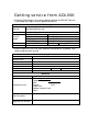
Getting service from ADLINK • Customer Satisfaction is the most important priority for ADLINK Tech Inc. If you need any help or service, please contact us. ADLINK Technology Inc. Web Site http://www.adlinktech.com Sales & Service service@adlinktech.com NuDAQ + USBDAQ nudaq@adlinktech.com NuDAM automation@adlinktech.com NuIPC nuipc@adlinktech.com NuPRO/EBC nupro@adlinktech.com +886-2-82265877 FAX +886-2-82265717 9F, No. 166, Jian Yi Road, Chungho City, Taipei, 235 Taiwan.
Table of Contents Chapter 1 Introduction ............................................................. 1 1.1 Features.............................................................................. 1 1.2 Applications ....................................................................... 2 1.3 Specifications..................................................................... 3 1.4 Software Support................................................................ 7 1.4.1 Programming Library.....................
4.1.4.4 Bus-mastering DMA Data Transfer....................................... 23 4.2 D/A Conversion ................................................................25 4.2.1 Software Update........................................................................28 4.2.2 Waveform Generation ..............................................................28 4.2.2.1 Waveform Generation Timing ............................................... 29 4.2.2.2 Trigger Modes..............................................
4.5.2.4 High-Hysteresis analog trigger condition.............................. 45 4.5.2.5 Low-Hysteresis analog trigger condition ............................... 45 4.6 Timing Signals ..................................................................46 4.6.1 System Synchronization Interface ...........................................47 Chapter 5 Calibration .............................................................48 5.1 Auto-calibration ..............................................................
How to Use This Guide This manual is designed to help you use/understand the DAQ/PXI-2500 SERIES high performance analog output multi-function cards. The manual describes the functions and the operation theory of the DAQ/PXI-2500 SERIES. It is divided into five chapters: Chapter 1, Introduction gives an overview of the product features, applications, and specifications. Chapter 2, Installation describes how to install the DAQ/PXI-2500 SERIES cards.
1 Introduction DAQ/PXI-2500 SERIES is an advanced analog output card based on the 32-bit PCI/PXI architecture. High performance designs and state-of-the-art technology make this card ideal for waveform generation, industrial process control, and signal analysis applications in medical, process control, etc. 1.
• D/A FIFO size: 8K samples for DAQ/PXI-2501, and 16K samples for DAQ/PXI-2502 • A/D FIFO size: 2K samples • Versatile trigger sources: software trigger, external digital trigger, analog trigger and trigger from System Synchronization Interface (SSI) • A/D Data transfer: software polling & bus-mastering DMA with Scatter/Gather • D/A Data transfer: software update and bus-mastering DMA with Scatter/Gather • A/D trigger modes: post-trigger, delay-trigger with re-trigger functionality • D/A outputs with wavefo
1.
Analog Input (AI) • Number of channels: 4 single-ended for DAQ/PXI-2502, 8 single-ended for DAQ/PXI-2501 • AD converter: LTC1416 • Max sampling rate: 400KS/s • Resolution: 14 bits • FIFO buffer size: 2K samples • Input range: Bipolar: ±10V, unipolar: 0~10V • Over voltage protection: Continuous ± 35V maximum • Input impedance: 1GΩ | 6pF • Trigger mode: Pre-trigger, post-trigger, middle-trigger, and delay trigger • Data transfers: Programmed I/O, and bus-mastering DMA with scatter/gather • Input coupling: DC
General Purpose Timer/ Counter (GPTC) • Number of channel: 2 Up/Down Timer/Counters • Resolution: 16 bits • Compatibility: TTL/CMOS • Clock source: Internal or external • Max source frequency: 10MHz Analog Trigger (A.
• Power Requirement: +5VDC; 1.
1.4 Software Support ADLINK provides versatile software drivers and packages for users’ different approach to building up a system. ADLINK not only provides programming libraries such as DLL for most Windows based systems, but also provide drivers for other software packages such as LabVIEW ®. All software options are included in the ADLINK CD. Non-free software drivers are protected with licensing codes.
1.4.3 D2K-OCX: ActiveX Controls We suggest customers who are familiar with ActiveX controls and VB/VC++ programming use PCIS-OCX ActiveX control component libraries for developing applications. PCIS-OCX is designed for Windows 98/NT/2000/XP. For more detailed information about PCIS-OCX, please refer to the user's guide in the CD. (\Manual_PDF\Software\D2K-OCX\D2K-OCX.PDF) The above software drivers are shipped with the board.
2 Installation This chapter describes how to install DAQ/PXI-2500 SERIES cards. The contents of the package and unpacking information that you should be aware of are outlined first. DAQ/PXI-2500 SERIES performs an automatic configuration of the IRQ, and port address. Users can use software utility, PCI_SCAN.EXE to read the system configuration. 2.
2.2 Unpacking Your DAQ/PXI-2500 SERIES card contains electro-static sensitive components that can be easily be damaged by static electricity. Therefore, the card should be handled on a grounded anti-static mat. The operator should be wearing an anti-static wristband, grounded at the same point as the anti-static mat. Inspect the card module carton for obvious damages. Shipping and handling may cause damage to your module.
2.3 DAQ/PXI-2500 SERIES Layout Figure 2.2 PCB Layout of DAQ-2502/2501 Figure 2.
2.4 PCI Configuration 1. Plug and Play: As a plug and play component, the board requests an interrupt number via its PCI controller. The system BIOS responds with an interrupt assignment based on the board information and system parameters. These system parameters are determined by the installed drivers and the hardware load seen by the system. 2. Configuration: The board configuration is done on a board-by-board basis for all PCI boards on your system.
3 Signal Connections This chapter describes the connectors of DAQ/PXI-2500 SERIES, and the signal connection between DAQ/PXI-2500 SERIES and external devices. 3.1 Connectors Pin Assignment DAQ/PXI-2500 SERIES is equipped with two 68-pin VHDCI-type connectors (AMP-787254-1). It is used for digital input / output, analog input / output, and timer/counter signals, etc. The pin assignments of the connectors are defined in Figure 3.1.1 and Figure 3.1.2.
AO_0 AO_1 AO_2 AO_3 AOEXTREF_A/AI_0 AI_1 EXTATRIG/AI_2 AOEXTREF_B/AI_3 AO_4/AI_4 AO_5/AI_5 AO_6/AI_6 AO_7/AI_7 AO_TRIG_OUTA AO_TRIG_OUTB GPTC1_SRC GPTC0_SRC GPTC0_GATE GPTC0_OUT GPTC0_UPDOWN RESERVED AFI1 PB7 PB5 PB3 PB1 PC7 PC5 DGND PC3 PC1 PA7 PA5 PA3 PA1 1 2 3 4 5 6 7 8 9 10 11 12 13 14 15 16 17 18 19 20 21 22 23 24 25 26 27 28 29 30 31 32 33 34 35 36 37 38 39 40 41 42 43 44 45 46 47 48 49 50 51 52 53 54 55 56 57 58 59 60 61 62 63 64 65 66 67 68 AGND AGND AGND AGND AGND AGND AGND AGND AGND AGND AGND A
Legend : Pin # Signal Name Reference AGND Direction Description 1~4 AO_<0..
4 Operation Theorm The operation theories of the DAQ/PXI-2500 series are described in this chapter. The functions include A/D conversion, D/A conversion, Digital I/O, and General Purpose Counter / Timer. This operation theory will help you understand how to configure and program the DAQ/PXI-2500 series.
Operation Theorem • 17
4.1 A/D Conversion When using an A/D converter, users should know the properties of the signal to be measured. In addition, users should setup the A/D configurations, including scan channels, input range, and polarities. The A/D acquisition is initiated by a trigger signal. The data acquisition will start once the trigger signal matches the trigger conditions. Converted data are queued into the FIFO buffer, and then transferred to the host PC's memory for further processing.
4.1.2 Software Polling This is the easiest way to acquire a single A/D data. The A/D converter performs one conversion whenever the dedicated software command is executed. The software would poll the conversion status and read the A/D data back when it is available. This method is suitable for applications that need to acquire A/D data in real time. In this mode, the timing of the A/D conversion is fully controlled by software. However, it would be difficult to maintain a fixed A/D sampling rate. 4.1.
4.1.3.1 Scan Timing and Procedure There are 4 counters that need to be specified prior to programmable scans: Counter Name Width Description Notes 24-bit Scan Interval, which defines the interval between each scan. Scan Interval = SI_counter 24-bit Sampling Interval, which defines the interval between each sampled channel. 24-bit Post Scan Counts, which defines how many scans to be performed with respect to each trigger. Delay_counter 16-bit Define the delay time for scan after trigger.
3 Scans, 4 Samples per scan (PSC_Counter=3) (Scan acquisition is performed in ascending sequence for enabled channels) Ch0 Ch1 C h2 Ch3 Trigger Ch0 C h1 Ch2 Ch3 C h0 Ch1 C h2 C h3 Scan_start AD_conversion Scan_in_progress Acquisition_in_progress Sampling Interval t= SI2_COUNTER/TimeBase Scan Interval T= SI_COUNTER/TimeBase Figure 4.1.1 Timing for Scan NOTE: 1. The maximum A/D sampling rate is 400KHz for DAQ/PXI-2500 series therefore the minimum setting of SI2_counter is 100. 2.
Timebase, external input (AFI-1), or General Purpose Timer/Counter Output 0/1. Post-Trigger or Delay-trigger Acquisition with retrigger Use post-trigger or delay-trigger acquisition with retrigger when users want to perform repeated scans with respect to the repeated triggers. Figure 4.1.4 illustrates an example. Two scans are performed after the first trigger signal, and then wait for the next trigger signal. When the trigger signal occurs, it performs 2 more scans.
(NumChan _Counter=4, PSC_Counter=3) Trigger Scan_start AD_conversion Scan_in_progress Acquisition_in_progress Delay until Delay_Counter reaches 0 Operation start Acquired & stored data (3 scans) Figure 4.1.3 Delay trigger (NumChan _Counter=4, SC_Counter=2, retrig_no=3) Trigger Scan_start AD_conversion Scan_in_progress Acquisition_in_progress Acquired & stored data (6 scans) Operation start Figure 4.1.4 Post trigger with retrigger 4.1.4.
The hardware temporarily stores the acquired data in the onboard Data FIFO buffer, then transfers the data to the user-defined DMA buffer in the host PC’s memory. Bus-mastering DMA utilizes the fastest available transfer rate of PCI-bus. Once the analog acquisition operation starts, control returns to your program. The DMA transfer mode is very complex to program. We recommend using a high-level program library to configure this card.
4.2 D/A Conversion DAQ/PXI-2500 series offers flexible and versatile analog output scheme to fit users’ complex field applications. In order to take full advantages of DAQ/PXI-2500 series, we suggest users carefully read the following contents. Architecture There are up to 8-channel of 12-bit Digital-to-Analog Converter (DAC) available in the DAQ/PXI-2502. Four D/A channels are packed into one D/A group, i.e., DAQ/PXI-2502 contains two D/A groups, and DAQ/PXI-2501 has only one D/A group. Figure 4.2.
Hardware controlled Waveform Generation FIFO is a hardware first-in first-out data queue, which holds temporary digital codes for D/A conversion. When DAQ/PXI-2500 SERIES operates in Waveform Generation mode, the waveform patterns are stored in FIFO, with 8K maximum samples. Waveform patterns larger than 8K are also supported by utilizing bus-mastering DMA transfer supported by PCI controller. Data format in FIFO is shown in Figure 4.2.2. Figure 4.2.
Setting up the DACs Before using the DACs, users should setup the reference source and its polarity. Each DAC has its own reference and polarity settings. For example; the internal voltage reference of D/A Group A is tied to internal +10V, however, users can still connect external reference thru AOEXTREF (pin 5 on CN2), for example to a +3.3V voltage source. Therefore, each DAC in D/A Group A has two reference options: 10V or 3.3V.
DAQ/PXI-2500 SERIES can generate standard and arbitrary functions, continuously or piece-wisely. Appendix A demonstrates possible waveform patterns generated by DAQ/PXI-2500 SERIES in combination with various counters, clock sources, and voltage references. 4.2.1 Software Update This method is suitable for applications that need to generate D/A output controlled by user programs. In this mode, the D/A converter generates one output once the software command is issued.
4.2.2.1 Waveform Generation Timing Six counters interact with the waveform to generate different DAWR timing, thus forming different waveforms. They are described in Table 4.2.3. Counter Name Width UI_counter 24-bit UC_counter 24-bit IC_counter 16-bit DLY1_counter 16-bit DLY2_counter 16-bit Trig_counter 16-bit Description Update Interval, which defines the update interval between each data output. Update Counts, which defines the number of data in a waveform.
NOTE: The maximum D/A update rate is 1MHz. Therefore the minimum setting of UI_counter is 40. 4 update counts, 3 iterations (UC _Counter=4, IC_Counter=3) Trigger UC_Counter=4 DAWR WFG_in_progress Delay until DLY1_Counter reaches 0 Delay until DLY2_Counter reaches 0 Delay until DLY2_Counter reaches 0 DA update_interval t= UI_Counter/Timebase 4 2 Output Waveform 0 -4 Operation start A single waveform IC_Counter = 3 Figure 4.2.
Delay-Trigger Generation Use delay-trigger when users want to delay the waveform generation after the trigger signal. The delay time is determined by DLY1_counter, as shown in Figure 4.2.5. The counter counts down on the rising edges of DLY1_counter clock source after the start trigger signal. When the count reaches zero, DAQ/PXI-2500 series starts to generate the waveform.
8 update counts, 1 iteration (UC _Counter=8, IC_Counter=1) Trigger DAWR WFG_in_progress Output Waveform Delay until DLY1_counter reaches 0 Operation start Figure 4.2.5 Delay-Trigger Generation 4 update counts, 2 iterations (UC _Counter=4, IC_Counter=2, Trig_Counter=3 , DLY2_Counter disabled, DLY2_Counter disabled) Trigger Ignored DAWR WFG_in_progress Output Waveform 2 4 0 Operation start a single waveform Figure 4.2.6 Post-Trigger with Retrigger Generation 4.2.2.
size of a single waveform were larger than that of the FIFO, it needs to be intermittently loaded from the host PC’s memory via DMA, thus PCI bandwidth would be occupied. If the value specified in UC_counter is smaller than the sample size of the waveform patterns, the waveform will be generated piece-wisely. For example, if users defined a 16-sample sine wave and set the UC_counter to 2, the generated waveform will be a 1/8-cycle sine wave for every waveform period.
DLY2_Counter in iterative Waveform Generation To expand the flexibility of Iterative Waveform Generation, DLY2_counter was implemented to separate consecutive waveform generations. The DLY2_counter starts counting down right after a single waveform generation is completed. When it reaches zero, the next iteration of waveform generation will start as shown in Figure 4.2.3. If users are generating waveform piece-wisely, the next piece of waveform will be generated.
4 update counts, infinite iterations (UC _Counter=4, IC_Counter disabled) Trigger DAWR WFG_in_progress Output Waveform 2 4 0 Operation start stop trigger Figure 4.2.9 Stop mode I (Assuming the data in the data buffer are 2V, 4V, 2V, 0V) 4 update counts, infinite iterations (UC _Counter=4, IC_Counter disabled) Trigger DAWR WFG_in_progress Output Waveform 2 4 0 Operation start stop trigger Figure 4.2.
4.3 General Purpose Digital I/O DAQ/PXI-2500 SERIES provides 24-line general-purpose digital I/O (GPIO) through a 82C55A chip. The 24-line GPIO are separated into three ports: Port A, Port B and Port C . High nibble (bit[7…4]), and low nibble (bit[3…0]) of each port can be individually programmed to be either inputs or outputs. Upon system startup or reset, all the GPIO pins are reset to high impedance inputs. For more information on programmable I/O chip 82C55A, please refer to http://www.intel.com.
4.4 General Purpose Timer/Counter Operation Two independent 16-bit up/down timer/counter are embedded in FPGA firmware for users applications. They have the following features: • Direction of counting can be controlled via hardware or software. • Selectable c ounter clock source from either internal or external clock up to 10MHz. • Programmable gate selection. • Programmable input and output signal polarities, either active-high or active-low.
4.4.2.1 Mode1: Simple Gated-Event Counting In this mode, the counter counts the number of pulses on the GPTC_CLK after the software start. Initial count value can be loaded via software. Current count value can be read-back by software at any time. GPTC_GATE is used to enable/disable counting. When GPTC_GATE is inactive, the counter halts the current count value. Figure 4.4.1 illustrates the operation with initial count = 5 in down-counting mode.
4.4.2.3 Mode3: Single Pulse-width Measurement In this mode, the counter counts the pulse-width of the signal on GPTC_GATE in terms of GPTC_CLK. Initial count can be loaded via software. After the software start, the counter counts the number of active edges on GPTC_CLK when GPTC_GATE is active. GPTC_OUT outputs high, and current count value can be read-back via software after the completion of the pulse-width measurement. Figure 4.4.3 illustrates the operation where initial count = 0 in up-counting mode.
4.4.2.5 Mode5: Single Triggered Pulse Generation This function generates a single pulse with programmable delay and programmable pulse-width following an active GPTC_GATE edge. These software programmable parameters can be specified in terms of periods of the GPTC_CLK input. Once the first GPTC_GATE edge triggers the single pulse, GPTC_GATE takes no effect until the software start is re-executed. Figure 4.4.5 illustrates the generation of a single pulse with pulse delay of two and pulse-width of four.
4.4.2.7 Mode7: Single Triggered Continuous Pulse Generation This mode is similar to mode 5, except that the counter generates continuous periodic pulses with programmable pulse interval and pulse-width following the first active edge of GPTC_GATE. Once the first GPTC_GATE edge triggers the counter, GPTC_GATE takes no effect until the software start is re-executed. Figure 4.4.7 illustrates the generation of two pulses with pulse delay of four and pulse-width of three.
4.5 Trigger Sources We provide flexible trigger selections in DAQ/PXI-2500 SERIES. In addition to software trigger, DAQ/PXI-2500 SERIES also supports external analog and digital triggers. Users can configure the trigger source for A/D and D/A processes individually via software. NOTE: A/D and D/A conversion share the same analog trigger. 4.5.1 Software-Trigger This trigger mode does not need any external trigger source. The trigger asserts right after users execute the specified function call.
Trigger Level digital setting Trigger voltage 0xFF 0xFE --0x81 0x80 0x7F --0x01 0x00 9.92V 9.84V --0.08V 0 -0.08V ---9.92V -10V Table 4.5.1 Analog trigger SRC1(EXTATRIG) ideal transfer characteristic The trigger signal asserts when an analog trigger condition is meet. There are five analog trigger conditions in DAQ/PXI-2500 SERIES. DAQ/PXI-2500 SERIES uses 2 threshold voltages: Low_Threshold and High_Threshold to compose 5 different trigger conditions.
4.5.2.2 Above-High analog trigger condition Figure 4.5.3 shows the above-high analog trigger condition, the trigger signal asserts when the input analog signal is higher than the High_Threshold voltage. The Low_Threshold setting is not used in this trigger condition. Figure 4.5.3 Above-High analog trigger condition 4.5.2.3 Inside-Region analog trigger condition Figure 4.5.
4.5.2.4 High-Hysteresis analog trigger condition Figure 4.5.5 shows the high-hysteresis analog trigger condition, the trigger signal asserts when the input analog signal level is higher than the High_Threshold voltage, where the hysteresis region is determined by the Low_Threshold voltage. Figure 4.5.5 High-Hysteresis analog trigger condition 4.5.2.5 Low-Hysteresis analog trigger condition Figure 4.5.
4.6 Timing Signals In order to meet the requirements for user-specific timing or synchronizing multiple boards, DAQ/PXI-2500 SERIES provides a flexible interface for connecting timing signals with external circuitry or other boards. The DAQ timing of the DAQ/PXI-2500 SERIES is composed of a bunch of counters and trigger signals in the FPGA on board. There are 7 timing signals related to the DAQ timing, which in turn influence the A/D, D/A process, and GPTC operation.
4.6.1 System Synchronization Interface SSI uses bi-directional I/O to provide flexible connections between boards. You can choose each of the 7 timing signals and which board to be the SSI master. The SSI master can drive the timing signals of the slaves. Users can thus achieve better synchronization between boards. Note that when power-up or reset, the DAQ board is reset to using its internal timing signals.
5 Calibration This chapter introduces the calibration process to minimize AD measurement errors and DA output errors. DAQ/PXI-2500 SERIES is factory calibrated before shipment. The onboard high precision band-gap voltage reference together with TrimDAC compensates for unwanted offsets and gain errors, caused by environment variation or component aging.
5.1 Auto-calibration The auto-calibration feature of DAQ/PXI-2500 SERIES facilitates users completing a calibration process, without the necessities for any external voltage references or measurement devices. The on-board auto-calibration circuitry is composed of a precision band-gap voltage reference, an ADC and a TrimDAC. TrimDAC is a multi-channel DAC that generates DC offsets that counteract the offsets from the main DACs.
6 Appendix A 6.1 Waveform Generation Demonstration Combined with 6 counters, selectable trigger sources, external reference sources, and time base, DAQ/PXI-2500 SERIES provides the capabilities to generate complex waveforms. Various modes shown below can be mixed together to generate waveforms that are even more complex. Although users can always load a new waveform to generate any desired waveform, we suggest using hardware capabilities to maximize both efficiency and flexibility.
Standard Function w. Frequency Variant Users can alter the frequency of generated waveforms by driving DAWR from external signal via AF0/AF1/SSI. The resultant updating rate should be kept within 1MHz. In this demo, iterative generation is used. Iterative Generation w. Intermediate Space Utilize DLY2_counter to separate consecutive waveform generations in iterative generation mode.
By feeding AFI0/AFI1 with PWM source, pulse train from VCO, or any time-varying digital signal, DAQ/PXI-2500 SERIES is capable of generating frequency modulated (FM) waveform. Since all four channels are synchronized in a D/A group, precise quadrature waveform generation is guarantied, provided the waveform are shifted 90-degree for the other channel. Phase difference of any degree can also be setup.
Warranty Policy Thank you for choosing ADLINK. To understand your rights and enjoy all the after-sales services we offer, please read the following carefully. 1. Before using ADLINK’s products, please read the user manual and follow the instructions exactly. When sending in damaged products for repair, please attach an RMA application form. 2. All ADLINK products come with a two-year guarantee,free of repair charge.
5. To ensure the speed and quality of product repair, please download an RMA application form from our company website www.adlinktech.com. Damaged products with RMA forms attached receive priority. For further questions, please contact our FAE staff. ADLINK: service@adlinktech.com Test & Measurement Product Segment: NuDAQ@adlinktech.com Automation Product Segment: Automation@adlinktech.com Computer & Communication Product Segment: NuPRO@adlinktech.com ; NuIPC@adlinktech.