PXIS-3320 PXIS-3320/1000W 15-Slot 6U PXI/CompactPCI Chassis with 500W/1000W Hot-swappable Power Supply User’s Manual Manual Rev. 2.00 Revision Date: October 27, 2006 Part No: 50-17024-1000 Advance Technologies; Automate the World.
Copyright 2006 ADLINK TECHNOLOGY INC. All Rights Reserved. Disclaimer The information in this document is subject to change without prior notice in order to improve reliability, design, and function and does not represent a commitment on the part of the manufacturer. In no event will the manufacturer be liable for direct, indirect, special, incidental, or consequential damages arising out of the use or inability to use the product or documentation, even if advised of the possibility of such damages.
Getting service from ADLINK Customer satisfaction is our top priority. Contact us should you require any service or assistance. ADLINK TECHNOLOGY INC. Web Site: Sales & Service: TEL: FAX: Address: http://www.adlinktech.com Service@adlinktech.com +886-2-82265877 +886-2-82265717 9F, No. 166, Jian Yi Road, Chungho City, Taipei, 235 Taiwan E-mail or fax this completed service form for prompt and satisfactory service.
Table of Contents List of Tables.......................................................................... iii List of Figures ......................................................................... v 1 Introduction ........................................................................ 1 1.1 1.2 Features............................................................................... 2 Unpacking Checklist ............................................................ 3 2 Chassis Overview..................
A Specifications.................................................................... 21 A.1 A.2 A.3 A.4 A.5 A.6 A.7 A.8 A.9 General .............................................................................. 21 Power Supply..................................................................... 21 System Monitoring ............................................................. 22 System LEDs ................................................................ 22 Buzzer/Alarm ....................................
List of Tables Table 3-1: LED indications ....................................................... 15 Table 4-1: Troubleshooting Power Failures .............................
List of Figures Figure 2-1: Figure 2-2: Figure 2-3: Figure 2-4: Figure 2-5: Figure 2-6: Figure B-1: Figure B-2: v PXIS-3320 front view ................................................. 5 PXIS-3320/1000W front view..................................... 6 PXIS-3320 and PXIS/1000W right view..................... 7 PXIS-3320 and PXIS/1000W top view....................... 7 PXIS-3320 and PXIS-3320/1000W rear view ............ 8 Backplane functions...................................................
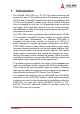
1 Introduction The ADLINK PXIS-3320 is a 19" 6U PXI chassis featuring one system slot and 14 PXI peripheral slots. The chassis is compliant with PXI and CompactPCI specifications and accommodates both 6U PXI and CompactPCI modules. An internal 10 MHz reference clock is available on all of the 14 PXI peripheral slots, as well as star trigger, PXI trigger bus, and PXI local bus. These functions are dedicated for users to facilitate synchronization among multiple peripheral modules.
1.1 Features 2 X Supports both 6U PXI and CompactPCI modules X PXI specifications Rev. 2.
1.2 Unpacking Checklist Before unpacking, check the shipping carton for any damage. If the shipping carton and/or contents are damaged, inform your dealer immediately. Retain the shipping carton and packing materials for inspection. Obtain authorization from your dealer before returning any product to ADLINK. Check if the following items are included in the package.
4 Introduction
2 Chassis Overview This section illustrates the mechanical dimensions of the PXIS3320 and PXIS-3320/1000W chassis, identifies the basic, and describes the backplane functions and features. 2.
Fan tray cover screw Fan tray cover Alarm reset button Power switch LEDs Fan tray cover Power supply modules Figure 2-2: PXIS-3320/1000W front view 6 Chassis Overview
2.2 Right View Handle Figure 2-3: PXIS-3320 and PXIS/1000W right view 2.
2.
2.5 Backplane overview The PXIS-3320 chassis comes with a 6U, 15-slot PXI backplane that supports one PXI system controller and 14 PXI/CompactPCI peripheral modules. This section illustrates the functions of the backplane.
Star Trigger Slot Slot 2 is designated as the Star Trigger (ST) slot. This slot features a dedicated trigger line between itself and slots 3 to 15. The star trigger delivers trigger signals with ultra-low skew (<1ns) to peripheral modules. To use the star trigger functionality, you must install a special star trigger controller in Slot 2. Peripheral Slots The PXIS-3320 chassis backplane accommodates up to fourteen 6U PXI/CompctPCI peripheral modules.
10 MHz Reference Clock The backplane supplies every peripheral slot with a 10 MHz system clock signal (PXI_CLK10). An independent clock buffer (having source impedance matched to the backplane and a skew of <1ns between slots) drives the clock signals to each peripheral slot. You can use this common reference clock signal to synchronize multiple modules in a measurement or control system or drive PXI_CLK10 from an external source through the PXI_CLK10_IN pin on the P2 connector of the star trigger slot.
12 Chassis Overview
3 Installation The chapter describes the procedures on how to install the system controller to the PXIS-3320 chassis. It also provides information on how to power up and monitor the system. 3.1 Calculating Power Consumption Before installing any modules into the PXIS-3320 chassis, calculate the total system power requirement and check the power saving requirements for each DC power source including the +5 V, +3.3 V, +12 V, and -12 V supply rail. Refer to Appendix A for the maximum usable power.
3.2 Installing the Chassis and Starting Up Follow the steps to power on the chassis. 1. For rackmount or bench-top installation, provide a sufficient space under the chassis for ventilation and make sure that the chasis is installed on a flat and stable surface. 2. Put the power switch in the standby (OFF) position. The power switch protrudes from the bezel when the system is in standby power mode. Refer to the illustration below. The front-panel power switch turns the system ON or OFF. 3.
9. Press the power switch. The amber LED and green LEDs on the upper right corner of the front panel light up. The chassis fans also start to rotate. NOTE Installation If the chassis fails to turn on, refer to Chapter 4: Troubleshooting and Preventive Maintenance for details.
3.3 Monitoring the System Light Emitting Diodes (LEDs) on the front panel tell you the power status, chassis temperature, and fan operations. Refer to Table 31 for details. LED Power Function DC rail voltages (+3.
3.5 Grounding the Chassis The backplane’s mounting holes may be grounded in two ways. First, the mounting holes labeled as GND with circle soldering mask can be connected to the signal ground plane of the backplane. Second, the mounting holes labeled as FGND with square soldering mask can be connected to the power ground plane (the earth), and is isolated from the signal ground. A proper signal and power wiring helps reduce the effects of ground loop and increases the accuracy of measurement.
3.7 Changing the Fans The PXIS-3320 chassis has ten 80 mm x 80 mm x 25 mm fans. These fans are installed in two decks of fan trays. Five fans are located at the bottom of the chassis for air intake, while the other five fans are installed on top of the chassis for air ventilation. The fan trays are hot-swappable. When a fan fails to operate, the alarm buzzer beeps and the fan LED flashes to alert you. Reset the alarm by pressing the alarm reset button, then replace the defective fan.
4 Troubleshooting and Preventive Maintenance 4.1 Troubleshooting for Power Failure of PXIS-3320 When the PXI-3320 chassis fails to turn on, refer to Table 4-1 for basic power troubleshooting. The table lists the most common cause for power failure and the recommends proces to correct the problem. Possible Causes The power cord is not connected to the power outlet. What to Do Make sure that the power cord is connected to a properly grounded and live electrical outlet.
4.2 Cleaning It is recommended that you clean the interior and exterior of the PXIS-3320 chassis regularly. To clean individual CompactPCI or PXI modules, refer to the documentation that came with the module. NOTE Always turn the chassis off and disconnect the power cord from the electrical socket before cleaning the chassis. Cleaning the Chassis Interior Use a dry, low-velocity stream of air to clean the interior of the chassis. Clean around components with a soft-bristle brush.
A Specifications A.1 General Complies with PXI specifications and accepts modules compliant with CompactPCI, PICMG 2.0 specifications. A.2 Power Supply X PICMG standards: PICMG 2.11-compliant X Input voltage: 100 to 240 VAC X Input frequency: 47 to 63 Hz X Output: 250 W (each) Specifications VDC Typical Maximum +5 V 25.0 A 33.0 A +3.3 V 18.0 A 33.0 A +12 V 5.0 A 5.5 A -12 V 0.
A.3 System Monitoring System LEDs LED Function/Setting Status Indication Power Voltage monitoring of +3.3 V, +5 V, +12 V, -12 V ON Power is supplied Temperature monitoring.
A.5 Physical X Number of slots: 15 (one system slot, 14 peripheral slots) X Dimensions: 484 mm x 295 mm x 398 mm (L x W x H) without handles X Weight: 23 kg A.6 Operating Environment Ambient temperature range Model Temperature PXIS-3320 0 to 50°C PXIS-3320/1000W 0 to 50°C Relative humidity: 10 to 90%, non-condensing A.7 Backplane X Backplane bare-board material: UL 94V-0 rated X Backplane connectors: Conforms to IEC-917 and IEC 10764-101, UL 94V-0 rated A.
24 Specifications
B Backplane Drawing and Pin Assignments B.1 Backplane Layout The following figures show the front and rear view of the PXIS3320 backplane. .
. Figure B-2: CBX-6015 rear view 26 Backplane Drawing and Pin Assignments
B.2 Backplane CBX-6015 Connectors Pin Assignments PXI Connectors Pin Assignments System Slot (Slot #1) P1 Pin Assignment Pin Z A B C D E F 25 GND +5V REQ64# ENUM# +3.3V +5V GND 24 GND AD[1] +5V V(I/O) AD[0] ACK64# GND 23 GND +3.3V AD[4] AD[3] +5V AD[2] GND 22 GND AD[7] GND +3.3V AD[6] AD[5] GND 21 GND +3.3V AD[9] AD[8] GND C/BE[0]# GND 20 GND AD[12] GND V(I/O) AD[11] AD[10] GND 19 GND +3.3V AD[15] AD[14] GND AD[13] GND 18 GND SERR# GND +3.
System Slot (Slot #1) P2 Pin Assignment Pin Z A B C D E F 22 GND PXI_BRSVA22 PXI_BRSVB22 PXI_BRSVC22 PXI_BRSVD22 PXI_BRSVE22 GND 21 GND CLK6 GND NC NC NC GND 20 GND CLK5 GND NC GND NC GND 19 GND GND GND SMBDATA SMBCLK SMBALERT- GND 18 GND PXI_TRIG3 PXI_TRIG4 PXI_TRIG5 GND PXI_TRIG6 GND 17 GND PXI_TRIG2 GND PRST# REQ6# GNT6# GND 16 GND PXI_TRIG1 PXI_TRIG0 DEG# GND PXI_TRIG7 GND 15 GND PXI_BRSVA15 GND FAL# REQ5# GNT5# GND 14 GND AD[35] AD[34]
Star Trigger Slot (Slot #2) P1 Pin Assignment Pin Z A B C D E F 25 GND +5V REQ64# ENUM# +3.3V +5V GND 24 GND AD[1] +5V V(I/O) AD[0] ACK64# GND 23 GND +3.3V AD[4] AD[3] +5V AD[2] GND 22 GND AD[7] GND +3.3V AD[6] AD[5] GND GND 21 GND +3.3V AD[9] AD[8] M66EN C/BE[0]# 20 GND AD[12] GND V(I/O) AD[11] AD[10] GND 19 GND +3.3V AD[15] AD[14] GND AD[13] GND 18 GND SERR# GND +3.3V PAR C/BE[1]# GND 17 GND +3.
Star Trigger Slot (Slot #2) P2 Pin Assignment Pin Z A B C D E F 22 GND PXI_BRSVA22 PXI_BRSVB22 PXI_BRSVC22 PXI_BRSVD22 PXI_BRSVE22 GND PXI_LBR3 GND 21 GND PXI_LBR0 GND PXI_LBR1 PXI_LBR2 20 GND PXI_LBR4 PXI_LBR5 PXI_STAR0 (2) GND 19 GND PXI_STAR2 (2) GND PXI_STAR3 (2) PXI_STAR4 PXI_STAR5 18 GND PXI_TRIG3 PXI_TRIG4 PXI_TRIG5 GND PXI_TRIG6 GND 17 GND PXI_TRIG2 GND N/C PXI_CLK10_IN PXI_CLK10 GND 16 GND PXI_TRIG1 PXI_TRIG0 N/C GND PXI_TRIG7 GND 15 GND
General Peripheral Slot (Slot #3~#15) P1 Pin Assignment Pin Z A B C D E F 25 GND +5V REQ64# ENUM# +3.3V +5V GND 24 GND AD[1] +5V V(I/O) AD[0] ACK64# GND 23 GND +3.3V AD[4] AD[3] +5V AD[2] GND 22 GND AD[7] GND +3.3V AD[6] AD[5] GND 21 GND +3.3V AD[9] AD[8] M66EN C/BE[0]# GND 20 GND AD[12] GND V(I/O) AD[11] AD[10] GND 19 GND +3.3V AD[15] AD[14] GND AD[13] GND 18 GND SERR# GND +3.3V PAR C/BE[1]# GND 17 GND +3.
General Peripheral Slot (Slot #3~#15) P2 Pin Assignment Pin Z A B C D E F 22 GND PXI_BRSVA22 PXI_BRSVB22 PXI_BRSVC22 PXI_BRSVD22 PXI_BRSVE22 GND 21 GND PXI_LBR0 GND PXI_LBR1 PXI_LBR2 PXI_LBR3 GND 20 GND PXI_LBR4 PXI_LBR5 PXI_LBL0 GND PXI_LBL1 GND 19 GND PXI_LBL2 GND PXI_LBL3 PXI_LBL4 PXI_LBL5 GND 18 GND PXI_TRIG3 PXI_TRIG4 PXI_TRIG5 GND PXI_TRIG6 GND 17 GND PXI_TRIG2 GND N/C PXI_STAR (2) PXI_CLK10 GND 16 GND PXI_TRIG1 PXI_TRIG0 N/C GND PXI_TRIG7 GND G
B.
B.
B.5 Miscellaneous Connectors Pin Assignments CN1, CN7, CN8, CN9: ATX-like DC Power input connectors NOTE Signal Name Pin # Pin # Signal Name V2SENSE 1 11 V2 (+3.3V) V2 (+3.3V) 2 12 V4 (-12V) GND 3 13 GND V1 (+5V) 4 14 INH# GND 5 15 GND V1 (+5V) 6 16 SRTN GND 7 17 GND FAL#1 8* 18* V3(+12V)SENSE DEG#1 9* 19 V1(+5V) SENSE Pin #8, #9, and #18 are not standard ATX power definitions.
J6 INH#: DC power inhibit signal J6 Pin # Signal Name 1 INH# 2 GND J8 RST#: System reset signal J8 Pin # Signal Name 1 RST# 2 GND J9 FAL#: Power supply fail input J9 Pin # Signal Name 1 FAL# 2 GND J5: Connector for LED power status J5 36 Name Pin # Pin # Name GND 8 7 +3.
CN5: SMB (System Management Bus) connector CN2 NOTE Pin # Name 1 IPMB_CLK 2 GND 3 IPMB_DATA 4 IPMB_PWR 5 ALERT The SMB is connected to the P2 of the system slot. JP1: 10 MHz Reference Clock Pin # Description Pin 1-2 (Default) Internal 10MHz system clock PXI_CLK10 Pin 2-3 External clock through the PXI_CLK10_IN on star trigger slot J2: POWER SENSE J2 Pin # Name 1 NC 2 +12V 3 +3.
38 Backplane Drawing and Pin Assignments
Important Safety Instructions Read and follow all instructions marked on the product and in the documentation before operating the system. Retain all safety and operating instructions for future use. X Read these safety instructions carefully. X Keep this user’s manual for future reference. X The equipment should be operated in an ambient temperature between 0°C to 50°C. X The equipment should be operated only from the type of power source indicated on the rating label.
X Openings in the chassis are provided for ventilation. Do not block or cover these openings. Make sure there is adequate space around the system for ventilation when setting up the work area. Never insert objects of any kind into the ventilation holes. X To avoid electrical shock, always unplug all power and modem cables from wall outlets before removing the system covers. X A Lithium-type battery is provided for the real time clock.
Warranty Policy Thank you for choosing ADLINK. To understand your rights and enjoy all the after-sales services we offer, please read the following carefully. 1. Before using ADLINK’s products please read the user manual and follow the instructions exactly. When sending in damaged products for repair, please attach an RMA application form which can be downloaded from: http://rma.adlinktech.com/policy/home.htm/. 2.
3. Our repair service is not covered by ADLINK's guarantee in the following situations: X Damage caused by not following instructions in the User's Manual. X Damage caused by carelessness on the user's part during product transportation. X Damage caused by fire, earthquakes, floods, lightening, pollution, other acts of God, and/or incorrect usage of voltage transformers. X Damage caused by unsuitable storage environments (i.e. high temperatures, high humidity, or volatile chemicals).