nanoX Starter Kit Quick Start Guide Manual Revision: 2.
Revision History Page 2 Revision Date 2.00 2.01 2010/11/25 2012/07/11 Changes Initial Release Add support for Type 10 modules (PCB rev.
Preface Copyright 2010-12 ADLINK Technology Inc. This document contains proprietary information protected by copyright. All rights are reserved. No part of this manual may be reproduced by any mechanical, electronic, or other means in any form without prior written permission of the manufacturer. Disclaimer The information in this document is subject to change without prior notice in order to improve reliability, design, and function and does not represent a commitment on the part of the manufacturer.
Environmental Responsibility (RoHS & WEEE) ADLINK is committed to fulfill its social responsibility to global environmental preservation through compliance with the European Union's Restriction of Hazardous Substances (RoHS) directive and Waste Electrical and Electronic Equipment (WEEE) directive. Environmental protection is a top priority for ADLINK.
Conventions Take note of the following conventions used throughout this manual to make sure that tasks and instructions are performed properly. Additional information, aids, and tips that help perform specific tasks. Critical information that users MUST know and instructions that users MUST perform to complete a task. Information to prevent physical injury, data loss, component damage, program corruption, etc. when trying to complete a specific task.
This page intentionally left blank.
Table of Contents Preface .......................................................................................................3 Table of Contents...........................................................................................7 1 1.1 1.2 1.3 Introduction..........................................................................................9 Overview .................................................................................................................................
This page intentionally left blank.
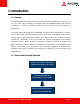
1 Introduction 1.1 Overview The nanoX Starter Kit is intended for testing and verification of COM Express systems based on Type 1 and Type 10 modules and complies with the PICMG® COM.0 R1.0 and R2.0 specification. It includes everything customers need to begin their own design and development.
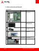
1.3 What's included in the nanoX Starter Kit? Standard Items No. Photo ADLINK P/N 1 91-77102-0010 nanoX-BASE Reference Carrier Board 2 29-90100-F000 10.1” LVDS flat panel display (1024 x 600) HSD100IFW1-A00 3 91-79203-0010 Flat Panel Transfer Board for LVDS to TTL signal conversion 4 92-94046-0010 ADD2 DVI Adapter card (FI-CH7307) 5 29-024L0-0010.
Standard Cabling Photo NanoX Starter Kit – Quick Start Guide Part No. Item Description 30-20243-2000 LVDS panel cable 30-20449-0000 FPTB LVDS-to-LVDS cable 30-30012-0000 SDVO flat cable 30-10057-5010 7P SATA cable 30-20171-1000 4-pin Molex to 2x SATA Power cable 30-01068-0000 USB 2.
Optional Items Type 1 Modules Photo Page 12 Part No. Item Description 91-72301-1030 nanoX-ML-53-512(G) Mini size COM Express Type 1 Module with Intel Atom Processor Z530 at 1.6GHz, 512 MB memory 91-72301-1130 nanoX-ML-53-512/4G(G) Mini size COM Express Type 1 Module with Intel Atom Processor Z530 at 1.6GHz, 512 MB memory and 4 GB SSD 91-72301-3130 nanoX-ML-51-512/4G(G) Mini size COM Express Type 1 Module with Intel Atom Processor Z510 at 1.
Type 10 Modules Photo NanoX Starter Kit – Quick Start Guide Part No. Item Description 91-72302-2010 nanoX-TC-E680-1G Mini size COM Express Type 10 Module with Intel Atom Processor E680 processor at 1.6GHz and PCH EG20T 91-72302-3010 nanoX-TC-E660-1G Mini size COM Express Type 10 Module with Intel Atom Processor E660 processor at 1.3GHz and PCH EG20T 91-72302-6010 nanoX-TC-E640-1G Mini size COM Express Type 10 Module with Intel Atom Processor E640 processor at 1.
2 Getting Started 2.
Remove the EPE foam layers and check accessory boxes contain the items below: NanoX Starter Kit – Quick Start Guide Page 15
2.2 Type 1 Module Installation If you intend to use a DVI monitor with the ADD2 DVI card, first install the SDVO flat cable onto the nanoX-ML module. Otherwise, skip ahead to Step 3. Install SDVO flat cable onto nanoX-ML (if required) Required items Step 1 Lift the locking mechanism on the nanoX-ML SDVO signal connector and insert the SDVO flat cable. Step 2 Press down on the lock on the SDVO connector to secure the flat cable.
Install heatsink onto nanoX-ML module Required items Step 3 Removed protective membranes from thermal pads Step 4 Assemble heatsink onto nanoX-ML module or NanoX Starter Kit – Quick Start Guide Page 17
Install heatsink onto nanoX-ML module (cont'd) Required items Step 5 Use one M2.
Install nanoX-ML module onto carrier board (cont'd) Required items Press down on the connector side of the module until it is firmly seated on the carrier board Step 7 Use two M2.
If you are not using a DVI monitor with the ADD2 DVI card, skip ahead to Section 2.4, DVI Display Interface Installation. Install SDVO flat cable onto carrier board (if necessary) Required items Step 8 Lift the locking mechanism on the nanoX-BASE SDVO input connector (CN30) and insert the SDVO flat cable.
2.
Install heatsink onto nanoX-TC module (con'td) Required items Step 2 Assemble heatsink onto nanoX-TC module Step 3 Use two M2.
Install nanoX-TC module onto carrier board Required items Step 4 Place the nanoX-TC module with heatsink onto the AB connector on the carrier board as shown Press down on the connector side of the module until it is firmly seated on the carrier board NanoX Starter Kit – Quick Start Guide Page 23
Install nanoX-TC module onto carrier board (cont'd) Required items Step 5 Use two M2.
If you not using a DVI monitor with the ADD2 DVI card, skip ahead to Section 2.5, LVDS Output using HannStar Flat Panel Display. Install SDVO flat cable onto carrier board (if required) Required items Step 6 Lift the locking mechanism on the nanoX-BASE SDVO input connector (CN30) and insert the SDVO flat cable. Insert the SDVO flat cable into nanoX-BASE SDVO input connector and press down on the locking mechanism Repeat for the SDVO output connector (CNX5).
2.4 DVI Display Interface Installation DVI Display using ADD2 DVI Adapter Card If you intend to use a DVI monitor with the ADD2 DVI Adapter Card, be sure to first install the SDVO flat cable as described above.
2.5 LVDS Output using HannStar Flat Panel Display To use the HannStar 10.1” LVDS flat panel display included with the nanoX-BASE Starter Kit, follow the instructions below. Install Flat Panel Display Required items Step 1 Set the nanoX-BASE Panel Power Jumper (JP3) is set to +3.
Install Flat Panel Display (cont'd) Required items Step 3 Connect the 34-pin female box header of the LVDS panel cable to CN6 of the nanoX-BASE (LVDS Output Connector) Step 9 Connect the 8-pin female box header of the LVDS panel cable to CN7 of the nanoX-BASE (Backlight Control Connector) Page 28 NanoX Starter Kit – Quick Start Guide
Using the Flat Panel Transfer Board Included with the nanoX Starter Kit is the Flat Panel Transfer Board (FPTB) which is intended for prototyping and verification of LVDS and TTL flat panel displays with COM Express systems. The FPTB is equipped with an LVDS-to-TTL converter to allow users to implement TTL displays with COM Express systems that support LVDS only. Onboard PWM circuitry supports backlight control for LVDS and TTL displays.
2.
Connect the Power Supply (cont'd) Required items Plug power cord into the power supply Connect the Keyboard and Mouse Plug keyboard and mouse connector into nanoX-BASE NanoX Starter Kit – Quick Start Guide Page 31
2.7 Powering Up the nanoX-BASE System To power up the nanoX-BASE system, follow the steps below. Powering Up the nanoX-BASE System Required items Press the Power Button SW1.
3 Using a TTL Flat Panel Display Included with the nanoX Starter Kit is the Flat Panel Transfer Board (FPTB) which is intended for prototyping and verification of LVDS and TTL flat panel displays with COM Express systems. The FPTB is equipped with an LVDS-to-TTL converter to allow users to implement TTL displays with COM Express systems that support LVDS only. Onboard PWM circuitry supports backlight control for LVDS and TTL displays.
3.
Connector Pin Definitions CN1: Power Connector (Floppy power connector) Pin Signal 1 +5V 2 GND 3 GND 4 +12V CN4: LVDS Input Connector (2x17 box header, 2.00 mm pitch) NanoX Starter Kit – Quick Start Guide Pin Signal Pin Signal 1 LVDS_CLK_A 2 LVDS_DTA_A 3 PNL_PWR 4 PNL_PWR 5 GND 6 LVDS_A-N0 7 LVDS_A-P0 8 VDD_EN 9 LVDS_A-N1 10 LVDS_A-P1 11 BL_EN_2 12 LVDS_A-P2 13 LVDS_A-N2 14 N.
CN5: TTL Output Connector (2x20 box header, 2.
CN6: LVDS Output Connector (2x17 box header, 2.00 mm pitch) Pin Signal Pin Signal 1 LVDS_CLK_A 2 LVDS_DTA_A 3 PNL_PWR 4 PNL_PWR 5 GND 6 LVDS_A-N0 7 LVDS_A-P0 8 VDD_EN 9 LVDS_A-N1 10 LVDS_A-P1 11 BL_EN_2 12 LVDS_A-P2 13 LVDS_A-N2 14 N.
Jumper Settings JP1: Backlight Voltage Jumper Status 1-2 +12V 3–4 Reserved 5–6 +5V* Jumper Status 1-2 +12V 3–4 Reserved 5–6 +5V 7-8 Reserved 9 - 10 +3.
3.3 Installation Jumper Settings Make sure the Backlight Voltage jumper (JP1) and Panel Voltage jumper (JP2) are correct for the display panel you are using. Set the LVDS/TTL Mode jumper (JP4) to TTL Output Active (short pins 1-2).Set the Backlight Control Mode jumper (JP5) to PWM or Voltage Level as appropriate for your display.
Connecting LVDS Input to FPTB Use the FPTB LVDS-to-LVDS cable (P/N 30-20449-0000) to connect the LVDS output connector on the nanoX-BASE (CN6) to the LVDS input connector on the FPTB (CN4).
TTL Output to Display Panel Make the appropriate cable to connect the TTL Output Connector (CN5) and Backlight Control Connector (CN8) on the FPTB to the target TTL display panel. FPTB Power Connector Connect the Floppy Drive power connector of your power supply to the FPTB Power Connector (CN1). Power Up the System Assemble the rest of your system as required and power it on. An example nanoX-BASE system with FPTB connected to a TTL display panel is shown below.
Technical Support Contact us should you require any service or assistance. ADLINK Technology, Inc. Address: 9F, No.166 Jian Yi Road, Zhonghe District New Taipei City 235, Taiwan 新北市中和區建一路 166 號 9 樓 Tel: +886-2-8226-5877 Fax: +886-2-8226-5717 Email: service@adlinktech.com Ampro ADLINK Technology, Inc. Address: 5215 Hellyer Avenue, #110, San Jose, CA 95138, USA Tel: +1-408-360-0200 Toll Free: +1-800-966-5200 (USA only) Fax: +1-408-360-0222 Email: info@adlinktech.com ADLINK Technology (China) Co., Ltd.
ADLINK Technology, Inc. (French Liaison Office) Address: 15 rue Emile Baudot, 91300 Massy CEDEX, France Tel: +33 (0) 1 60 12 35 66 Fax: +33 (0) 1 60 12 35 66 Email: france@adlinktech.com ADLINK Technology Japan Corporation Address: 〒101-0045 東京都千代田区神田鍛冶町 3-7-4 神田 374 ビル 4F KANDA374 Bldg. 4F, 3-7-4 Kanda Kajicho, Chiyoda-ku, Tokyo 101-0045, Japan Tel: +81-3-4455-3722 Fax: +81-3-5209-6013 Email: japan@adlinktech.com ADLINK Technology, Inc.