WAC 8-24 USER MAN FINAL 3/2/05 12:13 PM Page 1 ROOM AIR CONDITIONER Use and Care Manual AIRE ACONDICIONADO PARA HABITACIONES Manual de Uso y Mantenimiento Thank you for purchasing an Admiral® room air conditioner. Please read this “Use and Care Manual” carefully before installing and using this appliance. Keep this manual for future reference. Muchase gracias por comprar un aire acondicionado Admiral®. Lea atentamente el “Manual de Uso y Mantenimiento” antes de instalar y utilizar este producto.
WAC 8-24 USER MAN FINAL 3/2/05 12:13 PM Page 2
WAC 8-24 USER MAN FINAL 3/2/05 12:13 PM Page 3 TABLE OF CONTENTS Page Introduction . . . . . . . . . . . . . . . . . . . . . . . . . . . . . . . . . . . . . . . . . . . . . . . . . . 2 Parts Identification . . . . . . . . . . . . . . . . . . . . . . . . . . . . . . . . . . . . . . . . . . . 2-3 Air Conditioner Safety . . . . . . . . . . . . . . . . . . . . . . . . . . . . . . . . . . . . . . . . . 4-5 Electrical Specifications . . . . . . . . . . . . . . . . . . . . . . . . . . . . . . . . . . . . . . .
WAC 8-24 USER MAN FINAL 3/2/05 12:13 PM Page 4 INTRODUCTION Thank you for choosing this room air conditioner to cool your home. This USE AND CARE MANUAL provides information necessary for the proper care and maintenance of your new room air conditioner. If properly maintained, your air conditioner will give you many years of trouble free operation. To avoid installation difficulties, read instructions completely before starting.
WAC 8-24 USER MAN FINAL 3/2/05 12:13 PM Page 5 INTRODUCTION Part Identification ➤PART IDENTIFICATION Remote control model Front Panel Cabinet Control Panel Air Outlet Air Filter Speed Interior Air Inlet Grille Exterior Air Inlet Fresh Air Vent Lever Power Cord Remote Control Control Panel Airconditioner Timer High Mode Fan Speed Sa Mode ve Mi r d T im er Lo w Auto Note: The figures in this manual are based on the external view of a standard model.
WAC 8-24 USER MAN FINAL 3/2/05 12:13 PM Page 6 AIR CONDITIONER SAFETY Your safety and the safety of others are very important. We have provided many important safety messages in this manual and on your appliance. Always read and obey all safety messages. This is the SAFETY ALERT SYMBOL. This symbol alerts you to potential hazards that can kill or hurt you and others. All safety messages will follow the safety alert symbol and either the word “DANGER” or “WARNING.
WAC 8-24 USER MAN FINAL 3/2/05 12:13 PM Page 7 INSTALLATION REQUIREMENTS • The air conditioner should be connected to the appropriate electrical receptacle as shown in the chart on Page 6 ( Receptacle and Fuse Types). • The use of a time-delay fuse or time-delay circuit breaker is recommended. Power Supply Cord NOTE: Your unit’s device may differ from the one shown. • All wiring must comply with local and national electrical codes and be installed by a qualified electrician.
WAC 8-24 USER MAN FINAL 3/2/05 12:13 PM Page 8 ELECTRICAL SPECIFICATIONS 1. All wiring must comply with local and national electrical codes and must be installed by a licensed electrician. If you have any questions regarding the following instructions, contact a licensed electrician. ! Electric Shock Hazard If the air conditioner has a serial plate rating of 115 volts and up to and including 7.5 amps, the unit maybe on a fuse or circuit breaker with other devices.
WAC 8-24 USER MAN FINAL 3/2/05 12:13 PM Page 9 TIPS BEFORE INSTALLATION Your Room Air Conditioner unit is designed to be highly efficient and save energy. Follow these recommendations for greater efficiency. Your Room Air Conditioner was designed for easy installation in a single or double-hung window. NOTE: This unit is NOT designed for vertical (slider type) windows. 1. Select thermostat setting that suits your comfort needs and leave the thermostat at that chosen setting.
WAC 8-24 USER MAN FINAL 3/2/05 12:13 PM Page 10 INSTALLATION INSTRUCTIONS ! CAUTION E. Be certain the proper electrical outlet is within reach of the installation. Use only a single outlet circuit rated at proper current (see table 1 on page 4). All wiring should be in accordance with local and national electrical codes. ! Because the compressor is located on the controls side of the unit (right side), this side will be heavier and more awkward to manipulate.
WAC 8-24 USER MAN FINAL 3/2/05 12:13 PM Page 11 INSTALLATION INSTRUCTIONS 2. Preparation to Remove the Air Conditioner Slide-Out Chassis Airconditioner TIMER FAN SPEED A. Remove total of (4) Philips screws securing the chassis to the cabinet. There are (2) screws on each side. The set of screws closest to the front of the unit secure the front panel to the cabinet. The set of screw closest to the rear of the unit secure the cabinet to the chassis. See (Fig. 1).
WAC 8-24 USER MAN FINAL 3/2/05 12:13 PM Page 12 INSTALLATION INSTRUCTIONS 5. Installation of Mounting Brackets and First Sealing Strip (TOP VIEW) V-slot NOTE: Windows come in a variety of different styles. Therefore, it may be necessary to modify or improve your particular installation. Bracket Assembly A. Attach the bracket assembly to 90 angle support brackets (Fig. 5) using (2) 1 1/2" bolts Two bolts per bracket. Secure with the (2) 1/4" lock washers and (2) 1/4"nuts.
WAC 8-24 USER MAN FINAL 3/2/05 12:13 PM Page 13 INSTALLATION INSTRUCTIONS 6. Installation of the cabinet A. Align one hole in the bottom of the cabinet with one hole in the bracket assembly. Secure the cabinet to the bracket using (3) 1/4" screws provided. Repeat the same procedure on the opposite side of the cabinet. See (Fig. 10). 1/4" Screws B. Ensure the "L" shaped mounting channel is positioned in front of the sash.
WAC 8-24 USER MAN FINAL 3/2/05 12:13 PM Page 14 INSTALLATION INSTRUCTIONS 9. Complete the installation A. Cut the foam to fit the opening between the top of the inside and outside window. See (Fig. 13). B. Some installations may require additional sealing around the window and air conditioner. Check for any air leaks and seal where necessary. Foam Fig. 13 C. In very humid areas, the water removal may be excessive enough to overflow the unit or increase the noise of the air conditioner.
WAC 8-24 USER MAN FINAL 3/2/05 12:13 PM Page 15 OPERATING INSTRUCTIONS p g Mechanical control model ➤MECHANICAL CONTROL MODEL MODE The mode knob controls fan speeds and cooling speeds. To set desired cooling temperature, simply rotate the mode knob dial to the appropriate setting. THERMOSTAT The thermostat automatically controls the cooling cycle (compressor) of the air conditioner to maintain room temperature.
WAC 8-24 USER MAN FINAL 3/2/05 12:13 PM Page 16 OPERATING INSTRUCTIONS ➤ELECTRONIC CONTROL PANEL MODEL Electronic Control Panel Model Control Panel You can easily operate this air conditioner by pressing relevant button on the control panel as well as the remote control. Button The air conditioner will be started when it is energized or will be stopped when it is in operation, if you press this button.
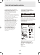
WAC 8-24 USER MAN FINAL 3/2/05 12:13 PM Page 17 OPERATING INSTRUCTIONS Remote control 1 BUTTON The appliance will be started when it is energized or will be stopped when it is in operation, if you press this button. 2 Mode BUTTON Used to select the operation mode. Each time the Mode button is pressed, the operation modeis changed in sequence: COOLING 3 3 2 Mode 9 Sa 8 Tim ve er High Mi r 4 5 6 High BUTTON Mid BUTTON Low BUTTON Used to select the Low fan speed mode.
WAC 8-24 USER MAN FINAL 3/2/05 12:13 PM Page 18 OPERATING INSTRUCTIONS Operating Instructions Remote control How to Insert the Batteries Remove the battery cover according to the arrow direction. Insert new batteries making sure that the (+) and (-) of battery are matched correctly. Reattach the cover by sliding it back into position. Note: Use 2 LR03 AAA (1.5volt) batteries. Do not use rechargeable batteries. Replace batteries with new ones of the same type when the display becomes dim.
WAC 8-24 USER MAN FINAL 3/2/05 12:13 PM Page 19 CARE AND MAINTENANCE When servicing the air conditioner, be sure to turn the mode switch to the "OFF" position and disconnect the power cord from the electrical outlet. ! CAUTION ! DO NOT forget to install the air filter. If the air conditioner is left to operate without the air filter, dust is not removed from the room and may cause your air conditioner to fail.
WAC 8-24 USER MAN FINAL 3/2/05 12:13 PM Page 20 TROUBLESHOOTING GUIDE Frequently, a problem is minor and a service call may not be necessary, use this troubleshooting guide for a possible solution. PROBLEM Air conditioner will not operate POSSIBLE CAUSE No power to the unit. SUGGESTED SOLUTION Check connection of power cord to power source. Check fuse or circuit breaker. Set FAN CONTROL to position other than "OFF". Inefficient or no cooling Dirty air filter. Clean or replace air filter.
WAC 8-24 USER MAN FINAL 3/2/05 12:13 PM Page 21 WARRANTY 5 YEAR FULL WARRANTY This product is warranted for 5 years from the date of original purchase. Any part which fails in materials or workmanship will be replaced within the warranty period. This warranty covers in home service. A copy of your proof of purchase, with date of purchase and product name included, is required to arrange this service repair.
WAC 8-24 USER MAN FINAL 3/2/05 12:13 PM Page 22 Introducción Gracias por elegir este aire acondicionado para enfriar su hogar. Este MANUAL DE USO Y MANTENIMIENTO proporciona la informaci n necesaria para cuidar y mantener en forma adecuada su nuevo aire acondicionado. Funcionar sin problemas durante muchos anos si le brinda el mantenimiento apropiado. Para evitar problemas al instalarlo, lea completamente las instrucciones antes de comenzar.
WAC 8-24 USER MAN FINAL 3/2/05 12:13 PM Page 23 Introducción ➤Identificación dePiezas las Piezas Identificaci n de las Modelo de Remoto controlador Panel Frontal Gabinete Entrada de Aire Interior Panel de Control Filtro de Aire Speed Rejilla de Entrada de Aire Interior Entrada de Aire Exterior Palanca de Aire Fresco Cable de Alimentaci n Control Remoto Panel de Control Air conditioner Timer Fan Speed Mode High Mode Sa ve Mi r d T im er Lo w Auto Nota: Las im genes de este manua
WAC 8-24 USER MAN FINAL 3/2/05 12:13 PM Page 24 Especificaciones eléctricas 1. Todos los cables deben cumplir con los c digos el ctricos locales y nacionales y los debe instalar un electricista licenciado. Si tiene preguntas relacionadas con las siguientes instrucciones, comun quese con un electricista licenciado. ! Peligro de Descarga El ctrica 2. Verifique el suministro de energ a disponible y resuelva cualquier problema con los cables ANTES de instalar y hacer funcionar esta unidad. 3.
WAC 8-24 USER MAN FINAL 3/2/05 12:13 PM Page 25 Consejos antes de la instalación El Aire Acondicionado para Habitaciones se ha disenado de modo tal que resulte f cil su instalaci n en ventanas armadas sencillas o dobles. NOTA: esta unidad NO se ha disenado para ventanas verticales (de tipo deslizante). Su unidad de Aire Acondicionado para Habitaciones se ha disenado para lograr un alto rendimiento y ahorrar energ a el ctrica. Siga las siguientes sugerencias para lograr un mayor rendimiento.
WAC 8-24 USER MAN FINAL 3/2/05 12:13 PM Page 26 Instrucciones de Instalación ! PRECAUCI N E. Aseg rese de instalar la unidad cerca de un tomacorriente el ctrico adecuado. Utilice un estime al corriente propio (lea tabla 1 en p gina 20) con circuito exclusivo para el aire acondicionado. Todos los cables deber n cumplir con los c digos el ctricos locales y nacionales.
WAC 8-24 USER MAN FINAL 3/2/05 12:13 PM Page 27 Instrucciones de Instalación 2. C mo quitar el armaz n deslizable del aire acondicionado A. Quite los 4 tornillos Philips que sujetan el armaz n al gabinete. Hay 2 tornillos de cada lado. Los tornillo s que est n m s cerca del frente de la unidad sujetan el panel frontal al gabinete. Los tornillos que est n m s cerca de la parte trasera de la unidad sujetan el gabinete al armaz n. Vea la (Fig. 1).
WAC 8-24 USER MAN FINAL 3/2/05 12:13 PM Page 28 Instrucciones de Instalación 5. Instalaci n de los Soportes Horizontales y de la Primera Tira Adhesiva Selladora NOTA: Existe una gran variedad de estilos de v entanas. Por lo tanto, es probable que se a necesario modificar o mejorar su propia instalaci n. A. Sujete el soporte horizontal a los soportes en escuadra (Fig. 5) con 2 pernos de 1 1/2". Hay dos pernos por soporte.
WAC 8-24 USER MAN FINAL 3/2/05 12:13 PM Page 29 Instrucciones de Instalación 6. Instalaci n del gabinete A. Alinee un agujero de la parte inferior del gabinete con un agujero del soporte ensambla do. Sujete el gabinete al soporte ensamblado con 3 de los tornillos de 1/4" proporcionados. Repita el mismo procedimiento del otro lado del gabinete. Vea la (Fig. 10). Tornillo de1/4" B. Aseg rese de que el canal de montaje en forma de L est delante del marco.
WAC 8-24 USER MAN FINAL 3/2/05 12:13 PM Page 30 Instrucciones de Instalación 9. Finalice la instalaci n A. Corte la espuma para que quepa en la abertura entre la parte superior del interior y exterior de la ventana. Vea la (Fig. 13). Espuma B. Es probable que algunas instalaciones necesiten tira selladora adicional alrededor de la ventana y el aire acondicionado. Verifique si hay alguna p rdida de aire y s llela si es necesario. Fig. 13 C.
WAC 8-24 USER MAN FINAL 3/2/05 12:13 PM Page 31 Instrucciones de Instalación MODE (Modo) La perilla de modo controla las velocidades de ventilador y de enfriamiento. Para fijar una temperatura de enfriamiento, simplemente haga rotar la perilla y col quela en el nivel deseado. Vea la Fig. 15. HIGH FAN 7 3 9 OL E R 1 MED FAN (Ventilador al Mediano) har que el aire circule a una velocidad mediana sin enfriar. LOW COOL Perilla de modo Fig.
WAC 8-24 USER MAN FINAL 3/2/05 12:13 PM Page 32 Instrucciones de Operación Este aire acondicionado se puede operar f cilmente con los botones del panel de control as como tambi n con el control remoto. Panel de Control Bot n (Encendido/Apagado) Si presiona este bot n, encender el aire acondicionado. Cuando el aire acondicionado esta de calefacci n, se per imprentar este bot n 3 minutos despu s.
WAC 8-24 USER MAN FINAL 3/2/05 12:13 PM Page 33 Instrucciones de Operación Control remoto 1 Bot n (Encendido/Apagado) El aparato se encender si est apagado o apagar cuando est en operaci n, si oprime este bot n. 2 Bot n MODE (Modo) Utilice este bot n para seleccionar el modo de operaci n. 3 Bot n Botones de ajuste de temperatura oprima para ajustar la temepratura del cuarto. oprima para programar la hora. 4 Bot n High Para ajustar el modo alta velocidad de ventilador.
WAC 8-24 USER MAN FINAL 3/2/05 12:14 PM Page 34 Instrucciones de Operación Control remoto Colocai n de las pilas Retire la tapa de las en el sentido de la flecha. Introduzca las pilas nuevas,con cuidado de que coincidan los polos(+)y(-). Vuelva a instalar la tapa,desliz ndola otra vez a su posici n. Nota: Utilice pilas 2 LR03 AAA(1.5V).No utilice pilas recargables.Sustituya las pilas por otras nuevas del mismo tipo cuando la pantalla aparezca atenuada.
WAC 8-24 USER MAN FINAL 3/2/05 12:14 PM Page 35 Cuidado y Mantenimiento Cuando repare el aire acondicionado, aseg rese de colocar la perilla de modo en OFF y luego desconectar el cable de alimentaci n del tomacorriente el ctrico. ! PRECAUCI N ! NO olvide instalar el filtro de aire. Si el aire acondicionado funciona sin el filtro de aire, el polvo no se puede eliminar de la habitaci n y es posible que la unidad se descomponga.
WAC 8-24 USER MAN FINAL 3/2/05 12:14 PM Page 36 Guá para la Solución de Problemas Generalmente los problemas son sencillos y es probable que no sea necesario llamar a un t cnico. Esta gu a puede ayudarlo a resolverlos. PROBLEMA El aire acondicionado no funciona CAUSA POSIBLE La unidad no recibe suministro el ctrico. SOLUCI N SUGERIDA Verifique si el cable de alimentaci n e st conectado al tomacorriente. Verifique el fusible o el cortacircuito.
WAC 8-24 USER MAN FINAL 3/2/05 12:14 PM Page 37 Garantía GARANTIA COMPLETA DE 5 ANOS Este producto se garantiza por 5 anos a partir de la fecha de la compra original. Cualquier parte que falle en materiales o la ejecuci n ser substituida dentro del per odo de la garant a. Esta garantia incluye servicio a domicilio. Una copia de su prueba de la compra, con la fecha de la compra del producto incluida, se requiere para acordar esta reparaci n del servicio.
WAC 8-24 USER MAN FINAL 3/2/05 12:14 PM Page 38
WAC 8-24 USER MAN FINAL 3/2/05 12:14 PM Page 39
WAC 8-24 USER MAN FINAL 3/2/05 12:14 PM Page 40 © 2005 Admiral , Kelon Air Conditioner Co., and Kelon USA, Inc. All rights reserved.