
User's Manual


4
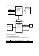
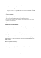
The mouse unit and base unit block diagrams are shown in Figures 2 and 3.
Processor
•
Mechanical
encoder interfaces
•
Data formatting
• Power control
•
ID selection
• LED
L button
R button
Radio frequency
transmitter and
integrated antenna
Battery
3D wheel
Mouse optical
ID button
Figure 2. Mouse Unit Block Diagram
Processor board
•
data demodulation
• data formatting
•
error checking
• computer interface
•
ID selection
• LED
Mouse data
Radio frequency
receiver and
integrated or
external antenna
Power
USB
interface
ID Button
Figure 3. Receiver Block Diagram
3.1.1.2 Performance Requirements
3.1.1.2.1 Product Performance Requirements
The end-to-end system performance requirements are contained in the Table 1 below.
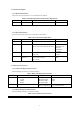
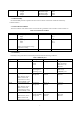
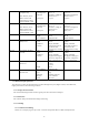
Table 1. System Performance Requirements
Rqmt No. Parameter Description Value
3.1.1.2.1.1 RF channel Operating frequency bands 27 MHz
3.1.1.2.1.2 RF channel Number of channels 1 channels
3.1.1.2.2 Mouse Unit Performance Requirements
Optical sensor, the precise sensor detects motion on hundreds of surfaces, including wood, plastic, or
even your pants leg.