
User's Manual Part 2


Advanced RF Technologies, Inc.
52
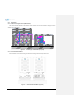
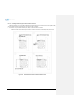
6.2.1.2 Wall mounting the ADX DAS HE
If the ADX HE chassis is being mounted to a wall, then allow clearance of at least 17” (430mm) on the top
(front side of HE) and 2” (51mm) on the bottom (rear side of HE) and 2” (51mm) on both sides and front for air
circulation.
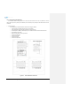
Mount procedure
- The following steps should be followed when wall mounting the ADX HE
Verify that the HE and Mounting hole are in good condition
Place the ADX HE against the wall and mark of the mounting holes
Drill holes(4holes, 18Φmm, 50mm depth) in the installation surface and insert the anchor bolts
Bolt the ADX HE to the wall
Make sure the ADX HE is securely attached
Connect the GND cable
Connect the RF cable
Connect the Power
Connect the Optic cable
Figure 6-2 ADX HE Wall Mount Instructions