
User's Manual Part 3


Advanced RF Technologies, Inc.
80
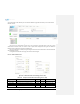
8.2.2.6.1 Band
Display the spectrum that is being used. The band column displays the bandwidth that has been used. The
downlink column displays the center frequency of the used downlink band. The uplink column displays the center
frequency of the used uplink band.
Figure 8-29 PCS Band Information (Status – Remote Module)
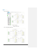
8.2.2.6.2 Power & Gain (Admin/User)
Display the Downlink output, Downlink/Uplink Attenuation, and Uplink Input/output.
Figure 8-30 Power & Gain (Admin)
Figure 8-31 Power & Gain (User)
Admin
o Input [dBm]: Displays the RF input level for Uplink only for the Remote Module.
o ALC Atten [dB]: The amount of attenuation used when ALC is activate.
o Atten [dB]: The amount of attenuation manually set by the user.
o [M]Output [dBm]: Output power of RF transceiver (1
st
stage amplification).
o [H]Output [dBm]: Output power of downlink HPA (2
nd
stage amplification).
User
o Input [dBm]: Displays the RF input level for Uplink only for the Remote Module.
o Atten [dB]: The amount of attenuation manually set by the user.
o Output [dBm]: Displays the total composite output power.