PSR-78-9533 MANUAL VERSION 0.3 3116 West Vanowen St. Burbank, CA 91505 Tel: 818-840-8131 Fax: 818-840-8138 www.adrftech.com Advanced RF Technologies, Inc.
Information in this document is subject to change without notice. Advanced RF Technologies, Inc. 1996-2016. All rights reserved. Please send comments to: E-Mail: Phone: Fax: info@adrftech.com (818) 840-8131 (800) 313-9345 (818) 840-8138 Address: Advanced RF Technologies, Inc. Attention: Technical Publications Department 3116 Vanowen St. Burbank, CA 91505 USA www.adrftech.com Advanced RF Technologies, Inc.
REVISION HISTORY Version 0.1 0.2 Author ADRF Ck Jo Descriptions Date Initial Release Revision Update 11/18/2016 01/17/2017 CHANGE LIST Version Change list Advanced RF Technologies, Inc.
TABLE OF CONTENTS 1. 2. Introduction ........................................................................................................................................................9 1.1 Highlights .....................................................................................................................................................9 1.2 Parts List........................................................................................................................................
25.4.2 Technology .........................................................................................................................................37 5.4.3 Band Selection ....................................................................................................................................37 5.4.4 SNMP ..................................................................................................................................................38 5.4.5 Location .......................
FIGURES Figure 1-1 Figure 1-2 Figure 2-1 Figure 2-2 Figure 2-3 Figure 2-4 Figure 2-5 Figure 2-6 Figure 2-7 Figure 2-8 Figure 2-9 Figure 2-10 Figure 4-1 Figure 4-2 Figure 5-1 Figure 5-2 Figure 5-3 Figure 5-4 Figure 5-5 Figure 5-6 Figure 5-7 Figure 5-8 Figure 5-9 Figure 5-10 Figure 5-11 Figure 5-12 Figure 5-13 Figure 5-14 Figure 5-15 Figure 5-16 Figure 5-17 Figure 5-18 Figure 5-19 Figure 5-20 Figure 5-21 Figure 5-22 Figure 5-23 Figure 5-24 Figure 5-25 Figure 5-26 Figure 5-27 Figure 5-28 Figure 9-1 PSR-78-953
TABLES Table 1-1 Table 2-1 Table 2-2 Table 3-1 Table 3-2 Table 8-1 Table 8-2 Table 8-3 Parts List .............................................................................................................................................10 LED Specifications ...............................................................................................................................17 External Alarm Port Pin Description ....................................................................................
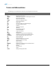
Terms and Abbreviations The following is a list of abbreviations and terms used throughout this document.
1. INTRODUCTION PSR-78-9533 bi-directional amplifier (BDA) extends the coverage area of radio communications in buildings and RF shadow environments. The unit features low noise figure and wide dynamic range. 1.
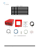
1.2 Parts List Table 1-1 Label Quantity A B C D E F G H I 1 1 1 1 1 1 6 1 1 Parts List Description PSR-78-9533 Wall Mount Bracket Mounting Bracket Template AAI Alarm Cable AC Power Cable Ethernet Cable (Crossover) Anchor Bolt Ground Cable Documentation CD A B E F Figure 1-1 Advanced RF Technologies, Inc.
1.3 Quick View Ground Terminal Server Port (4.3-10 Female) Donor Port (4.3-10 Female) Sever CPL (DL Output Monitor Port,-30dB) Donor CPL (UL Output Monitor Port, -30dB) AAI Alarm Port Ethernet Port (RJ-45) ADRF-BBU Battery Port AC Input Port Air Vent Hole Heat Sink Figure 1-2 Advanced RF Technologies, Inc.
1.4 Warnings and Hazards WARNING! ELECTRIC SHOCK Opening the PSR-78-9533 could result in electric shock and may cause severe injury. WARNING! EXPOSURE TO RF Working with the repeater while in operation, may expose the technician to RF electromagnetic fields that exceed FCC rules for human exposure. Visit the FCC website at www.fcc.gov/oet/rfsafety to learn more about the effects of exposure to RF electromagnetic fields.
Lithium Battery: CAUTION. RISK OF EXPLOSION IF BATTERY IS REPLACED BY INCORRECT TYPE. DISPOSE OF USED BATTERIES ACCORDING TO INSTRUCTIONS. Ethernet Instructions: This equipment is for indoor use only. All cabling should be limited to inside the building. Preclude indications that Home/ personal use are prohibited. Use of unauthorized antennas, cables, and/or coupling devices not conforming with ERP/EIRP is prohibited.
FCC Part 90 Class A WARNING. THIS is NOT a CONSUMER device. It is designed for installation by FCC LICENSEES and QUALIFIED INSTALLERS. You MUST have an FCC LICENSE or express consent of an FCC Licensee to operate this device. You MUST register Class B signal boosters (as defined in 47 CFR 90.219) online at www.fcc.gov/signal-boosters/registration. Unauthorized use may result in significant forfeiture penalties, including penalties in excess of $100,000 for each continuing violation. FCC Part 15.
RSS-GEN, Sec. 7.1.2– (detachable antennas) This radio transmitter (identify the device by certification number, or model number if Category II) has been approved by Industry Canada to operate with the antenna types listed below with the maximum permissible gain and required antenna impedance for each antenna type indicated. Antenna types not included in this list, having a gain greater than the maximum gain indicated for that type, are strictly prohibited for use with this device.
Part 90.635 requirement Antennas must be installed in accordance with FCC 90.635. With 17 dBi gain antennas the height of the antenna above average terrain (HAAT) must not exceed 80 m. For different gain antennas refer to the relevant rules. ◈LABEL WARNING◈ Advanced RF Technologies, Inc.
2. 2.1 OVERVIEW LED PSR-78-9533 LED indicator lights are located on the inside of the repeater towards the bottom. Below the LED indicators is a button that is used to trigger the door open alarm.
2.3 Cable Connection 2.3.1 AC Power AC power is accepted through a standard 3-wire male plug (MS3106A-22-2S) with phase, neutral, and ground leads. The AC power is wired to a high-efficiency DC switching power supply which is UL approved. The AC port is located at the bottom of the repeater and has a free range input of 100-240V AC.
2.3.2 External Alarm Figure 2-5 External Alarm port This port should be connected only to the fire alarm control panel.
2.3.3 RF Figure 2-6 RF ports The RF connections are made via two 4.3-10 female connectors. The RF connector labeled “DONOR” must be connected to the antenna pointing towards the base station. The DONOR port can receive both 700 and 800MHz public safety signals. The RF connection labeled “SERVER” must be connected to the antenna facing the area to be covered by the BDA. The repeater has a single SERVER port that supports both 700 and 800MHz public safety signals.
2.3.4 Back Up Battery Port This port connects to the ADRF-BBS/BBL-24 (24V battery backup unit) via a dedicated cable provided by the ADRF. Figure 2-7 Battery Backup Port If an ADRF-BBS/BBL-24 is connected to the repeater, the battery switch on the PSU must be switched to the ON position. This will enable the repeater to charge the ADRF-BBS/BBL-24 battery backup unit when AC power is present.
2.3.5 Grounding A ground cable is included in the box. The grounding terminal is located at the lower right-hand side of the BDA. The grounding cable should be properly connected before powering on the equipment. Figure 2-9 Ground Cable Terminal Ground terminals located on the side of the repeater and can support a ground cable up to 1.25mm² (16AWG) in diameter and should be permanently connected to a grounding bar. 2.3.
3. 3.1 ALARMS Message Board Alarms and Notifications Table 3-1 Message Board Alarms and Notifications Parameters AC Fail DC Fail Temperature Current System Halt DSP Fault OSC DL Signal not detected DL Signal Low Input Overload Out of band Overload Synthesizer Lock Fail DL RF Power Overpower VSWR Heartbeat Reboot Factory setting Door 3.
3.3 DL RF Power Input + gain does not match the output level. (default delta of 6 dB) Overpower Output level is above the max output levels. AGC On case (Soft: AGC Level + 1~2dB, Hard: AGC Level + >2dB) AGC Off case (Soft: max output level + 1~2dB, Hard: max output level + >2dB) VSWR Power is being reflected back to the repeater. Threshold = output power - 8dB. For example, if the repeater is outputting 24dBm and detects 16dBm of return power, then the VSWR will be triggered.
External Alarm Name System Component Malfunction - Set Condition DL Return Power Hard Fail DL/UL Over Power Hard Fail DL/UL Input Overload Hard Fail Over Current Hard Fail Over Temperature Hard Fail DSP Hard Fail Out-band Overload Hard Fail 3.3.2 External Alarm Input interface User Alarm Input Port No External Alarm In User Alarm 1 ALARM IN 1 TBD Advanced RF Technologies, Inc.
4. 4.1 INSTALLATION Installation Procedures 4.1.
Antenna Separation/Isolation The separation between the donor and server antennas is necessary to prevent oscillation. Oscillation occurs when the signal entering the system continually re-enters, due to the lack of separation between the donor and server antennas. In other words, the signal is being fed back into the system. This creates a constant amplification of the same signal. As a result, the noise level rises above the signal level. PSR-78-9533 4.
DO NOT APPLY A.C. POWER TO THE BDA UNTIL CABLES ARE CONNECTED TO BOTH PORTS OF THE BDA AND THE ANTENNAS. 1. To mount on a wall. Using appropriate screws and anchors and attach the BDA to the wall at the four mounting holes. 2. Ensure that the isolation between the donor antenna and the serving antennas is at least 15 dB greater than the BDA gain. 3.
5. PSR-78-9533 WEB-GUI SETUP The Web-GUI allows the user to communicate with the repeater either locally or remotely. To connect to the repeater locally, you will need a laptop with an Ethernet port and an RJ-45 crossover cable. To connect to the repeater remotely, you will need to have an active internet connection via an external modem or LAN. 5.
5.2 Status Tab Figure 5-2 Advanced RF Technologies, Inc.
5.2.1 Band Info The Band Info section displays frequency information along with the corresponding bandwidths that have been set from the Install tab. Input levels for each channel are also displayed in this section. Figure 5-3 Band Info Display 5.2.2 Power & Gain This section displays the Input, Gain, and Output for both downlink and uplink. Figure 5-4 Power & Gain Display Input [dBm] – Displays the in-band Downlink/Uplink signal level. The system will display “--.-“ when the input level is < -90 dBm.
5.2.3 Alarms This section displays the alarm status for System alarms, RF Alarms, and Power alarms. If an alarm is present in the system, then the color of the alarm tab will change according to the type of failure. Figure 5-5 Alarm Display 5.2.
5.3 Control Tab Figure 5-7 Advanced RF Technologies, Inc.
5.3.1 General Setting The General Setting section allows the user to enable/disable amplifiers and the ALC routine.
5.3.
5.4 Install Tab 5.4.1 Install Figure 5-12 Install Page Advanced RF Technologies, Inc.
5.4.2 Technology This section allows the user to set the repeater mode to either use PS700, PS800, or PS700+PS800. Figure 5-13 Technology The following choices are available from the dropdown: • PS700 (758-775MHz) • PS800 (851-861MHz) • PS700+PS800 (758-861MHz) 5.4.3 Band Selection Figure 5-14 Band Selection Band selection allows the user specify the desired frequncies by inputting the center frequencies and selecting the bandwidths.
5.4.4 SNMP Figure 5-15 SNMP The SNMP section allows you to specify the Site ID and Description. The Site-ID is the code that is used to identify the repeater. 5.4.5 Location This section allows the user to input the latitude and the longitude of the repeater. Figure 5-16 Location Setting 5.4.6 Modem Box Setting This section allows the user to specify alternative Repeater IP, Subnet Mask, and Gateway settings. These settings are enabled when the Host/Remote switch is set to the Remote position.
5.4.8 Location Info / Installer Info This section allows the user to specify the address of the repeater and also the information of the installer. Figure 5-19 Repeater Location Info / Repeater Installer Info 5.4.9 Date & Time This section allows the user to specify the current date and time. Figure 5-20 Date & Time Setting Advanced RF Technologies, Inc.
5.5 System The System tab allows the user to perform firmware updates, upload closeout packages, view any changes to the system, backup existing configuration, and add/remove user accounts, and change the login credentials of the Administrator. 5.5.1 System: Account 5.5.1.1 System: Account – Account Management The Account Management section allows the Administrator to delete any user accounts.
This section displays system events that have taken place. The User Log displays who has made the changes, the time and date of when the event took place, and what changes were made to the system. Figure 5-24 System – User Log Advanced RF Technologies, Inc.
5.5.3 System – Update To perform a firmware update, click on the Update tab and the following screen will appear. Figure 5-25 System – Update Click on the Choose File button and locate the firmware file. Click on the Upgrade button to perform the firmware update. Once the firmware update is complete, the following popup message will appear: Figure 5-26 Pop-up Message after System Update is Complete 5.5.4 System – Backup & Restore The backup section allows the user to save the settings of the repeater.
5.6 Help If an internet connection is available, clicking on the Help Tab will redirect the user to our Technical Support page. Figure 5-28 Help 5.7 Logout Clicking the Logout button will log the current user off the system. 6. MAINTENANCE GUIDE FOR PSR-78-9533 REPEATER 6.1 Periodic Inspection Checklist Check for loose connections between the repeater and antennas. If connections are loose, make sure that all connections are tightly fastened properly. Cables and connectors are in good condition.
7. 7.1 WARRANTY AND REPAIR POLICY General Warranty The PSR-78-9533 carries a Standard Warranty period of two (2) years unless indicated otherwise on the package or in the acknowledgment of the purchase order. 7.2 Limitations of Warranty Your exclusive remedy for any defective product is limited to the repair or replacement of the defective product. Advanced RF Technologies, Inc. may elect which remedy or combination of remedies to provide in its sole discretion. Advanced RF Technologies, Inc.
8. SPECIFICATIONS 8.
Operating at Ambient Temperature 8.2 -40°F to +140°F (-40°C to +60°C) Mechanical Specifications Table 8-2 Parameters Mechanical Specifications Specifications Comments Dimensions W x D x H 11.0 x 9.0 x 21.67 in (w/o mounting bracket) Weight 55 lbs (w/o mounting bracket) RF Connector 4.3-10 (Female) Weather Resistances IP66 8.
9. MECHANICAL DRAWING Figure 9-1 Advanced RF Technologies, Inc.
10. APPENDIX 10.1 Shutdown Retry Logic The function of the built-in shutdown routine is to protect the repeater from any further damage from a hardfail that the system may be experiencing. Within 5 seconds of a hard-fail alarm being detected, the repeater will start the shutdown routine. The repeater will shut down by powering of the HPAs (high-powered amplifiers) for 30 seconds. After 30 seconds have elapsed, the repeater will power on the HPAs and check to see if the hard-fail alarm still exists.