
User's Manual


Advanced RF Technologies, Inc.
vi
Figure 2-3 AC Input Port................................................................................................................................ 16
Figure 2-5 Battery Backup Port...................................................................................................................... 16
Figure 2-6 RF port ......................................................................................................................................... 17
Figure 4-1 SDR-ICS-43 Wall Mount ................................................................................................................ 20
Figure 4-2 Ground Cable Connection............................................................................................................. 20
Figure 4-3 RF Repeater Oscillation................................................................................................................. 21
Figure 4-4 Line of Sight to the eNode-B(or BTS)............................................................................................. 22
Figure 5-1 Login page.................................................................................................................................... 23
Figure 5-2 Status Tab .................................................................................................................................... 24
Figure 5-3 Band Display ................................................................................................................................ 24
Figure 5-4 Power & Gain Display ................................................................................................................... 25
Figure 5-5 Alarm Display ............................................................................................................................... 25
Figure 5-6 Message Board............................................................................................................................. 26
Figure 5-7 Install, Power and modem Status.................................................................................................. 26
Figure 5-8 Repeater Info / Repeater Location / Technical Support / Installer Contact Info.............................. 27
Figure 5-9 Control page ................................................................................................................................ 28
Figure 5-10 General Setting ............................................................................................................................ 28
Figure 5-11 System ......................................................................................................................................... 29
Figure 5-12 Pop-up message when Reboot button is pressed .......................................................................... 29
Figure 5-13 Pop-up message when Factory Setting button is pressed .............................................................. 29
Figure 5-14 SNMP Trap................................................................................................................................... 29
Figure 5-15 Gain Control Setting ..................................................................................................................... 30
Figure 5-16 ICS Control Setting........................................................................................................................ 30
Figure 5-17 Alarm Threshold Setting ............................................................................................................... 30
Figure 5-18 Install page................................................................................................................................... 31
Figure 5-19 SNMP........................................................................................................................................... 32
Figure 5-20 Location Setting ........................................................................................................................... 32
Figure 5-21 Remote Ethernet Settings............................................................................................................. 33
Figure 5-22 Auto Installation........................................................................................................................... 33
Figure 5-23 Repeater Location Info / Repeater Installer Info............................................................................ 34
Figure 5-24 Date & Time Setting ..................................................................................................................... 34
Figure 5-25 Band Selection ............................................................................................................................. 35
Figure 5-26 System: Account- Account Management ...................................................................................... 35
Figure 5-27 System: Account- New Account .................................................................................................... 36
Figure 5-29 System: Account- Change Password.............................................................................................. 36
Figure 5-30 System- Closeout Package ............................................................................................................ 37
Figure 5-31 System- Closeout Package after the file upload............................................................................. 37
Figure 5-32 System – User Log ........................................................................................................................ 37
Figure 5-33 System – Update .......................................................................................................................... 38
Figure 5-35 System Backup............................................................................................................................. 39
Figure 5-36 Help ............................................................................................................................................. 39
TABLES
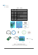
Table 1-1 Parts List ........................................................................................................................................ 9
Table 2-1 RF Module LED Specifications....................................................................................................... 15
Table 3-1 Message Board Alarms and Notification ....................................................................................... 18
Table 3-2 Alarms Threshold ......................................................................................................................... 19
Table 8-1 Electrical Specifications ..................................................오류! 책갈피가 정의되어 있지 않습니다.