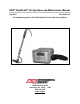
ADS® FlowShark® HV Operation and Maintenance Manual July 2010 QR 775005 A2 An introductory guide to the ADS FlowShark HV Portable Velocity Meter ® A DIVISION OF ADS LLC 4940 Research Drive Huntsville, AL 35805 USA (256) 430-3366 www.
ADS FlowShark HV O&M Manual © 2010 ADS Environmental Services. All rights reserved. ADS®, ADS Environmental Services®, and FlowShark® are registered trademarks of ADS LLC. All other brand and product names are trademarks or registered trademarks of their respective holders. Notice of Proprietary Information The information contained herein represents the latest information available at the time of publication.
ADS FlowShark HV O&M Manual Table of Contents Introduction ..................................................................................................5 Product Warranty .........................................................................................7 New Product Warranty...........................................................................7 Out of Warranty Product Repairs...........................................................7 Troubleshooting Fee ...................................
ADS FlowShark HV O&M Manual 5 Introduction The ADS® FlowShark® HV (hand-held velocity) is a battery-powered, portable device designed for taking instantaneous peak flow velocity measurements in wastewater collection systems, irrigation channels, and streams. The FlowShark HV includes a control unit, sensor, and battery charger. This manual explains how to setup, operate, maintain, and troubleshoot the FlowShark HV.
ADS FlowShark HV O&M Manual 7 Product Warranty This section includes warranty information for the ADS FlowShark HV. New Product Warranty All new products manufactured by ADS will be free from defects in material and workmanship for up to two (2) years following the date of shipment from ADS. During this warranty period, upon satisfactory proof of a defect, the product may be returned for repair or replacement, at ADS’s sole option.
ADS FlowShark HV O&M Manual THIS IS THE ONLY WARRANTY FOR ADS PRODUCTS. NO OTHER WARRANTY IS EXPRESSED OR IMPLIED, INCLUDING FITNESS FOR A PARTICULAR PURPOSE OR MERCHANTABILITY. PRODUCT REPAIR OR REPLACEMENT IS THE ONLY REMEDY. IN NO EVENT WILL ADS BE RESPONSIBLE FOR ANY DIRECT, INDIRECT, CONSEQUENTIAL, OR SPECIAL DAMAGES.
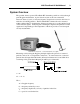
ADS FlowShark HV O&M Manual 9 System Overview The portable, battery-powered FlowShark HV determines peak flow velocity through pulse Doppler measurement. A piezoelectric crystal on the sensor transmits ultrasonic bursts (signals) of a known frequency in rapid succession into the flow for reflection off existing particles. The FlowShark HV evaluates the echos returned within a defined time to determine the distances from the sensor to the particles based on the reflected signals.
ADS FlowShark HV O&M Manual Operational and Environmental Conditions The technical specifications of the FlowShark HV and the flow and hydraulic conditions at the measurement location determine the operational success and/or performance level of the FlowShark HV.
ADS FlowShark HV O&M Manual 11 Flow Depth Flow levels must exist at a depth of at least 2 to 3 inches (51 to 76 mm) above the bottom center of the pipe or channel to successfully obtain velocity measurements. Channel Wall/Water Surface Do not measure velocity within 1.5 inches (38 mm) of the channel wall or flow surface.
ADS FlowShark HV O&M Manual 13 Setup and Operation Properly setting up and operating the FlowShark HV are critical to obtaining the most accurate and reliable velocity measurements. Developing a basic understanding of the control unit keyboard and display before taking measurements is also essential to accessing and interpreting the results correctly. These combined skills and knowledge are fundamental to performing measurement activities effectively and efficiently.
ADS FlowShark HV O&M Manual Connecting the Sensor to the Control Unit Connect the sensor to the control unit by removing the protective cap from the corresponding port on the unit and then inserting and screwing in the connector from the sensor cable into the port. When measurement is complete, unscrew and remove the sensor connector from the control unit and replace the protective cap onto the port.
ADS FlowShark HV O&M Manual 15 Modifying the Parameter Settings The lower level screens provide access to parameter settings that may be modified to provide additional information, compensate for flow conditions, support associated hardware, and address other relevant issues involved in velocity measurement activities. The default parameters are set for the FlowShark HV at the factory. Under normal conditions, it should not be necessary to access or modify the parameter settings on the control unit.
ADS FlowShark HV O&M Manual Understanding the Keys on the Control Unit The following table provides general functional descriptions for the keys on the control unit. Each key serves multiple functions. The current function of a key depends on the current content displayed on the control unit screen.
ADS FlowShark HV O&M Manual 17 Note: If acclimation and stabilization do not occur within 5 minutes, please contact an ADS representative for further assistance. The sensor has been calibrated for measuring velocity in water. However, if velocity measurements will be taken in another kind of medium in which the speed of sound differs from that of water (4872 feet per second (1485 mps) at 20°C (68°F)), contact ADS for assistance in modifying the calibration factor accordingly when setting the parameters.
ADS FlowShark HV O&M Manual time period over which the average was calculated will display until a new running average velocity is initiated or the control unit display is turned off or goes off automatically. ADS also recommends an ISO standard that includes several other methods for calculating average velocity using the individual velocity measurements obtained through the FlowShark HV: ISO 748:2007, Hydrometry – Measurement of Liquid Flow in Open Channels Using Current-Meters or Floats.
ADS FlowShark HV O&M Manual Poor Reflection Quality in Flow The following histogram displays a very wide range of frequencies with no stable peak, producing a quality rating of less than 30%. The velocity readings displayed are essentially too low, and the histogram suggests that the low quality rating may be the result of a low concentration of reflective particles that are too small for detection.
ADS FlowShark HV O&M Manual 21 Maintenance Perform routine maintenance on the FlowShark HV to maintain optimal performance and maximize the life of the components. The maintenance interval and scope may vary based on operational and environmental conditions and practical experience obtained over time. However, the following are some general maintenance procedures ADS recommends implementing for the FlowShark HV: Clean the control unit and sensor after every measurement.
ADS FlowShark HV O&M Manual Troubleshooting The following tables contain general techniques for troubleshooting and resolving problems that may occur with the FlowShark HV. Problem FlowShark HV will not turn on. Possible Causes Battery voltage is too low. Possible Solutions Recharge battery. Surrounding temperature is outside the specified operating temperature. Warm or cool equipment. Problem Measurement value will not display or is fluctuating.
ADS FlowShark HV O&M Manual 25 Technical Specifications The following tables include the technical specifications for the components comprising the FlowShark HV and the CE guidelines. When applicable, certain specifications may reflect using the equipment under optimal operational and environmental conditions. Individual specifications also may include details concerning possible external influences or conditions that may affect the velocity data obtained.
ADS FlowShark HV O&M Manual Sensor The following table contains the specifications for the sensor probe for velocity measurement. Material Rating Stainless steel and polyurethane IP68 (NEMA 6) Removable Rod Material: Aluminum (telescopic) with bubble level Emitting Frequency 750 kHz Measurement Window Length: 28 to 63 inches (0.7 to 1.6 meters) Position: 2.36 inches (6 cm) along the horizontal axis in front of the sensor Length: 1.18 inches (3 cm) Diameter: 0.63 inches (1.