ADS® FlowShark® Pulse Operation and Maintenance Manual March 2009 QR 775004 A1 An introductory guide to the ADS® FlowShark® Pulse Meter Valid as of Software Revision No. 4.
ii ADS FlowShark Pulse O&M Manual © 2009 ADS® LLC. All rights reserved. ADS®, ADS Environmental Services®, and FlowShark® are registered trademarks of ADS LLC. NIVUS® is a registered trademark of NIVUS GmbH. Java™ is a trademark of Sun Microsystems, Inc. All other brand and product names are trademarks or registered trademarks of their respective holders. Notice of Proprietary Information The information contained herein represents the latest information available at the time of publication.
Table of Contents iii Table of Contents Chapter 1 Warranty and Certifications 1-1 Declaration of Conformity ................................................................................... 1-2 Product Warranty ................................................................................................. 1-3 New Product Warranty................................................................................... 1-3 Out of Warranty Product Repairs.......................................................
iv ADS FlowShark Pulse O&M Manual Chapter 5 Delivery, Maintenance, and Handling 5-1 Delivery and Receipt ............................................................................................ 5-2 Maintenance ......................................................................................................... 5-3 Handling............................................................................................................... 5-5 Storage ....................................................
Table of Contents v Chapter 8 Parameter Settings 8-1 Quick Start Guide for Setting Parameters ............................................................ 8-2 Basics for Setting Parameters .............................................................................. 8-3 Operation Mode (RUN) ....................................................................................... 8-5 Display Menu (EXTRA) ......................................................................................
vi ADS FlowShark Pulse O&M Manual Chapter 11 Troubleshooting 11-1 Chapter 12 Materials and Chemical Resistance 12-1 Chemical Resistance Legend ............................................................................. 12-3 Resistance .................................................................................................... 12-3 Material Names ............................................................................................
CHAPTER 1 Warranty and Certifications This chapter includes the Declaration of Conformity, the ADS® warranty, and all required certifications for the ADS FlowShark® Pulse. Please notice that the certifications included in this chapter identify the FlowShark Pulse as the OCM Pro CF. The FlowShark Pulse is a version of the NIVUS® OCM Pro CF designed specifically for ADS. In all aspects related to certification, the FlowShark Pulse is identical to the OCM Pro CF.
1-2 ADS FlowShark Pulse O&M Manual Declaration of Conformity EC Declaration of Conformity Pursuant to z the EC Low Voltage Directive 73/23/EEC, Annex III z the EC EMC Directive 89/336/EEC, Annex I and II z the EC Directive 94/9/EC: Equipment and protective systems intended for use in potentially explosive atmospheres (ATEX) We hereby declare that the design of the Description: Measuring device OCM Pro with active sensor as delivered complies with the above regulations and following EC directives and
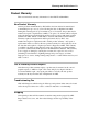
Warranty and Certifications 1-3 Product Warranty This section includes warranty information for the ADS FlowShark Pulse. New Product Warranty All new products manufactured by ADS will be free from defects in material and workmanship for up to two (2) years following the date of shipment from ADS. During this warranty period, upon satisfactory proof of a defect, the product may be returned for repair or replacement, at ADS’s sole option.
1-4 ADS FlowShark Pulse O&M Manual THIS IS THE ONLY WARRANTY FOR ADS PRODUCTS. NO OTHER WARRANTY IS EXPRESSED OR IMPLIED, INCLUDING FITNESS FOR A PARTICULAR PURPOSE OR MERCHANTABILITY. PRODUCT REPAIR OR REPLACEMENT IS THE ONLY REMEDY. IN NO EVENT WILL ADS BE RESPONSIBLE FOR ANY DIRECT, INDIRECT, CONSEQUENTIAL, OR SPECIAL DAMAGES.
Warranty and Certifications 1-5 Ex-Approval Transmitter The approval is valid only when the corresponding indicator displays on the transmitter nameplate.
1-6 ADS FlowShark Pulse O&M Manual The approval is valid only when the corresponding indicator displays on the transmitter nameplate.
Warranty and Certifications 1-7 The approval is valid only when the corresponding indicator displays on the transmitter nameplate.
1-8 ADS FlowShark Pulse O&M Manual The approval is valid only when the corresponding indicator displays on the transmitter nameplate.
Warranty and Certifications 1-9 The approval is valid only when the corresponding indicator displays on the transmitter nameplate.
1-10 ADS FlowShark Pulse O&M Manual Ex-Approval Sensors The approval is valid only when the corresponding indicator displays on the transmitter nameplate.
Warranty and Certifications 1-11 The approval is valid only when the corresponding indicator displays on the transmitter nameplate.
CHAPTER 2 Use and Specifications Please read this instruction manual thoroughly. It contains all the information necessary to configure and operate the FlowShark Pulse for proper operation. This manual is written primarily for qualified technical staff that have adequate knowledge of measurement technology, automation technology, information technology, and wastewater hydraulics. Reading and following the instructions in this manual before initial start-up will help ensure success in device configuration.
2-2 ADS FlowShark Pulse O&M Manual Use in Accordance with the Requirements The ADS FlowShark Pulse and corresponding sensors are designed for measuring slightly- to heavily-polluted flow in partially-filled and full pipes or other similar applications. Please adhere to the measurement specifications designated in this chapter. Monitoring flow under conditions falling outside the documented specifications of the equipments’ capabilities without prior written permission of ADS occurs at the owner’s risk.
Use and Specifications Max. outer inductivities allowed Max. outer capacities allowed Sensor connections 2 mH 380 nF 1 mH 430 nF 0.5 mH 510 nF 0.2 mH 660 nF Ignition protection type intrinsically-safe EEx ia IIB Clamps D1...D5, E1...E5 for connection of accompanying sensors only F1...F5, G1...G5 Type POA/...OCL/... according to TÜV 03 ATEX 2262 Max. values per circuit: U0 = 10.5 V I0 = 640 mA rectangular characteristic Max. outer inductivities allowed: 0.12 mH Max.
2-4 ADS FlowShark Pulse O&M Manual Specifications Transmitter Power Supply 100 to 240 V AC, +10% /-15%, 47 to 63 Hz or 24 V DC ± 15%, 5% residual fluctuation Power Consumption Maximum 20 VA Wall-Mount Enclosure • Material: Polycarbonate • Weight: approximately 6.
Use and Specifications 2-5 Combi Sensor/Pipe Insertion Sensor Measurement Principle • Ultrasonic transit time (depth measurement) – Combi Sensor only • Piezoresistive pressure measurement (depth measurement) – Combi sensor only • Correlation with digital pattern detection (flow velocity) Measurement Frequency 1 MHz Protection Rating IP 68 Ex-Approval (optional) II 2 G EEx ib IIB T4 Operating Temperature -4° to 122° F (-20° to +50° C) (104° F (40° C) in Ex Zone 1) Storage Temperature -22° t
2-6 ADS FlowShark Pulse O&M Manual depth measurement via water-ultrasonic (and redundant pressure measurement), and temperature measurement to compensate for the effect of temperature on the velocity of sound (combi sensor only) Types of Construction Medium Contacting Materials • Wedge sensor for installation on pipe bottom • Insertion sensor for installation through pipe wall with nozzle and cutting ring Polyurethane, stainless steel 1.
Use and Specifications Sonic Beam Angle ±5 degrees Temperature Measurement Measurement Range -4° to 140° F (-20° to +60° C) Measurement Error ±0.
2-8 ADS FlowShark Pulse O&M Manual Accessories (Option) Pressure Compensation Element For connection of sensors with integrated pressure measurement cell Memory Card SanDisk compact flash card with 128-MB maximum capacity Read-out Adapter Adapter for PCMCIA interfaces, primarily for data read-out via laptop Read-out Uunit USB interface for PC connection Pipe Mounting System For temporarily clamping air-ultrasonic or combi sensors in pipes DN 200 - 800 (~ID 6 – 32 inches)
CHAPTER 3 Safety and Identification Following are the descriptions or interpretations for the general safety or danger symbols corresponding to the special notes referenced throughout this manual.
3-2 ADS FlowShark Pulse O&M Manual Device Identification The instructions in this manual pertain only to the FlowShark Pulse.
Safety and Identification 3-3 Replacement Parts and Accessories ADS does not certify replacement parts or accessories that are not supplied by ADS. Installing and/or using such products could adversely affect the operation of the equipment. Therefore, users are responsible for all damages incurred as a result of using parts or accessories supplied by any manufacturer other than ADS.
3-4 ADS FlowShark Pulse O&M Manual Emergency and Safety Procedures In case of an emergency, terminate power in one of the following ways: z Turn off power at the source from the which the FlowShark Pulse is receiving power. z Set the slide switch for power on the FlowShark Pulse to the OFF position.
Safety and Identification 3-5 User’s Responsibilities Obtain all local operating permits required and observe the provisions contained within the permits.
CHAPTER 4 System Overview and Operation The FlowShark Pulse is a long-term monitoring system designed for flow measurement, flow control (Model 20 transmitters only), data storage, and (optional) remote access via TCP/IP communication. This device primarily is designed for use in slightly- to heavily-polluted flow of various compositions. It can function in partially-filled and full pipes of various shapes and dimensions.
4-2 ADS FlowShark Pulse O&M Manual Combination Sensor The FlowShark Pulse uses a combination (combi) sensor that can simultaneously determine both flow velocity and flow depth. A combi sensor may contain up to two 2 depth measurement devices: a water-ultrasonic device and/or a hydrostatic (pressure) device.
System Overview and Operation 4-3 Adding the sensor offset to the measured depth value (h1) determines the depth total (h). The sensor offset represents the distance from the bottom of the pipe to the sensor crystal position. The measured depth value represents the distance from the crystal to the flow surface. Pressure Depth Measurement The combi sensor may have an integrated hydrostatic depth measurement device.
4-4 ADS FlowShark Pulse O&M Manual particles may exit the measurement range before a subsequent measurement can occur; and new particles may enter into the measurement range. Fig. 4-3 Conditions at second signal detection The DSP checks both of the received reflection patterns for similarities using the cross-correlation method. All existing signal differences are rejected so that the two similar, but temporarily offset, signal patterns remain for velocity evaluation.
System Overview and Operation 4-5 Figure 4-6 Calculated 3-dimensional flow profile Flow rate can be calculated and displayed based on the flow velocity distribution, pipe shape and dimensions, and flow depth. It also is available for display or output to another device through either a free programmable analog signal or a pulse signal.
4-6 ADS FlowShark Pulse O&M Manual Air-Ultrasonic Depth Sensor An air-ultrasonic depth sensor uses horizontal sensor crystals to determine the distance (range) from the sensor to the flow surface based on the time difference between transmitting and receiving a pulse reflected off the flow surface (the transittime method). The flow depth is calculated by subtracting the range and the sensor offset from the pipe height.
System Overview and Operation 4-7 Pipe Insertion Sensor The pipe insertion sensor primarily is used to measure flow velocity in closed pipes that remain full, eliminating the need for a depth measurement device. When installed, the sensor mounts perpendicular to the pipe and extends from the outside of the pipe, through the pipe wall, and slightly into the flow. The pipe insertion sensor uses the same technology for measuring velocity as the velocity component of the combi sensor.
4-8 ADS FlowShark Pulse O&M Manual Device Versions The FlowShark Pulse transmitter and the supporting combi, pipe insertion, and airultrasonic sensors are available in different versions. The tables below provide a brief overview of the various options. Transmitter Transmitters vary primarily based on the power supply, Ex-protection, and enclosure construction. The article number posted on a label on the bottom of the enclosure identifies the device type.
System Overview and Operation 4-9 Sensors Several sensor models support the FlowShark Pulse. Individual models may vary based on Ex-protection, cable length, and unique construction. The item number identifying the sensor model is printed on the sensor where the cable enters the sensor body and on a nameplate at the end of the cable. A transparent tube on the end of the cable provides protection for the nameplate against weather conditions and abrasion.
4-10 ADS FlowShark Pulse O&M Manual Sensor Connection K Cable end pre-configured for connection to 1K/1R and 2K/2R FlowShark Pulse units L Cable end pre-configured for connection to 3K and 4K FlowShark Pulse units (pressure compensation element required) Pipe Length 0 (applies only to combi sensor) 2 20 centimeters (8 in) – standard 3 30 centimeters (12 in)– minimum length for stop valve) 4 40 centimeters (16 in) G 20 centimeters (8 in) with threaded extension Fig.
CHAPTER 5 Delivery, Maintenance, and Handling This chapter contains information regarding shipping, maintaining, handling, storage, and disposal of the FlowShark Pulse transmitter and sensors.
5-2 ADS FlowShark Pulse O&M Manual Delivery and Receipt Delivery of a typical FlowShark Pulse measurement system includes the following: z Instruction manual including all the necessary steps to correctly install and operate the measurement system and the certificate of conformity z FlowShark Pulse Model 10 or 20 transmitter z Ultrasonic sensor: combi sensor or pipe insertion sensor with threaded cutting ring (consisting of spigot nut, cutting ring, and pipe double nipple) Additional accessories, su
Delivery, Maintenance, and Handling 5-3 Maintenance Because the measurement system primarily exists in a wastewater environment, it may be contaminated with hazardous germs. Therefore, please take special precautions when handling the transmitter, cables, sensors, and associated equipment. The FlowShark Pulse is extremely durable, is virtually maintenance-free, and does not require calibration.
5-4 ADS FlowShark Pulse O&M Manual To identify the zero point for the pressure measurement cell, consider measuring the current depth level with a yardstick, ruler, or similar tool without removing the sensor from the flow. However, keep in mind that this method can produce errors. Inserting the ruler (or yardstick) into the flow creates a surge that could lead to measurement errors based on the current flow velocity.
Delivery, Maintenance, and Handling 5-5 Handling This sections includes instructions and procedures for the FlowShark Pulse and sensors concerning storage, transport, and disposal.
CHAPTER 6 Installation Reading and following the installation instructions before initial start-up will help ensure success in flow measurement and device configuration. Do not initiate startup until installation is complete and verified. If any problems occur during installation, connection, or configuration, please contact an ADS representative. Installation should be performed only by qualified personnel according to all statutory standards, regulations, and technical rulings.
6-2 ADS FlowShark Pulse O&M Manual Transmitter Installation and Connection General When selecting a mounting location for the transmitter, avoid locations exhibiting or near the following conditions: z Direct sunlight (use weatherproof cover, if necessary) z Heat-emitting objects (maximum ambient temperature of 104°F (40°C)) z Objects generating strong electromagnetic fields (such as frequency converters or electric motors that consume significant power) z Corrosive chemicals or gas z Mechanical
Installation 6-3 Enclosure Dimensions Fig 6-1 Wall mount enclosure Transmitter Connection General The FlowShark Pulse transmitter is available in 2 different versions: z Model 10 standard version z Model 20 with supplemental connections for up to 3 flow velocity sensors, digital inputs, and additional analog inputs/outputs plus controller function Both models have the same clamp terminal marking. However, the Model 20 transmitter includes additional connections.
6-4 ADS FlowShark Pulse O&M Manual Model 20 Transmitter: z 2 glands M20 x 1.5 z 3 glands M16 x 1.5 z 2 plugs M20 x 1.5 z 2 plugs M16 x 1.5 Use the glands supplied to connect the following outer cable cross-sections: z M16 x 1.5: 3.5 mm – 10.5 mm (0.138 – 0.413 in) z M20 x 1.5: 6.0 mm – 14.0 mm (0.236 – 0.591 in) To use a cable with a diameter outside of the specified tolerance, use a gland that ensures IP 65 minimum protection.
3 4 6 7 = 0.9 8 9 AI3 AI4 GND AO3 AO4 GND AO AO serial interface 10-36V GND potentials isolated from each other: DE1/2, DC-, AE1 ... 4, AA1 ...
6-6 ADS FlowShark Pulse O&M Manual Sensor Installation and Connection Choosing a Suitable Location for Sensor Installation Clear and stable hydraulic conditions are essential for obtaining accurate sensor measurements.
Installation 6-7 Angle of the Curve in the Pipe v ≤ 1m/s v > 1m/s α ≤15° L ≥ min. 3x DN L ≥ min. 5x DN α ≤45° L ≥ min. 5x DN L ≥ min. 10x DN α ≤90° L ≥ min. 10x DN L ≥ min.
6-8 ADS FlowShark Pulse O&M Manual = Error! Changes in slope = changes in flow profile = Distance depending on slope and flow velocity reading l = min. 20 x diameter Figure 6-7 Error caused by changes in slope = Error! Installed in draw-down Depth measurement may fail + velocity and depth measurement may be erroneous ? = Critical measurement point, not recommended! Flow begins to fall (or sink) = Distance l = min.
Installation 6-9 3 ~ ~ 11.8 in max. WSP ~ ~ 3.94 in 1 2 (1) = Wave formation on water surface behind the sensor Æ error message from following air-ultrasonic sensor (2) (2) = Good (might have to be installed 0.
6-10 ADS FlowShark Pulse O&M Manual Sensor Installation When installing the sensors, use only non-corrosive fastening materials and fasten the sensors both securely and tightly. To avoid disturbances from electrical interference, do not locate sensor cables close (or parallel) to an engine (motor) or main power lines. Combi Sensor Fasten the sensor through the four holes on the front and reverse sides of the ground plate (Figure 6-12, detail Y).
Installation 6-11 bottom center of the pipe. Higher depth levels and/or flow velocities may produce erroneous measurements if the sensor is not installed properly. When using a combi sensor with water-ultrasonic and pressure measurement capability, environmental conditions, such as the Bernoulli effect, may produce erroneous measurements in the presence of high flow velocities and low depth levels.
6-12 ADS FlowShark Pulse O&M Manual 1 Pipe Bottom 2 Silicone or Similar 3 Sensor 4 Mounting Plate Figure 6-13 Suggestion for installing countersunk combi sensors Make sure the combi sensor is not covered with or deposited in filling material. This could result in signal attenuation or erroneous measurements. Run the sensor cable along the pipe bottom from the back of the sensor to the pipe wall.
Installation 6-13 Figure 6-15 Hints on cable layout (1 represents the protective cover) Do not bend the standard signal cable in more than a 3.94-inch (10-cm) radius. Bending it into a smaller radius could break the cable and, for certain sensors, produce kinks in the cable and create obstructions in the air compensation hose (resulting in erroneous depth measurements).
6-14 ADS FlowShark Pulse O&M Manual Make sure the horizontal part of the sensor is flush with the pipe wall once installed (Figure 6-16, far left). Figure 6-16 Proper pipe insertion sensor installation (left – represents a proper installation; center – represents a poor installation due to build-up; right – represents a poor installation due to faulty readings or sensor failure) Install the sensor so that the beveled side is facing upstream.
Installation 6-15 1 Cutting ring inside and outside 2 Thread 3 Inner cone 4 Inner thread of spigot nut Figure 6-18 Greasing parts Air-Ultrasonic Sensors Install the air-ultrasonic sensor with clamping using an pipe mounting system. To install the sensor using this mounting system, run the mounting sheet located in the pipe vertex (crown) through the cut-out (Item 4 on Figure 6-19) in the air-ultrasonic sensor prior to final assembly.
6-16 ADS FlowShark Pulse O&M Manual 4-inch (10-cm) Dead Band 79 inches (200 cm) h max Figure 6-20 Installing the air-ultrasonic sensor L 4 in (10 cm) FLOW Figure 6-21 Mounting example For a permanent installation, secure the air-ultrasonic sensor to the top of the pipe with 3 stainless steel screws (M5) and corresponding dowels (Figure 6-22).
Installation 6-17 1.57 in (40 mm) .29 in (7.5 mm) .94 in (24 mm) X .69 in (17.5 mm) 12.60 in (320 mm) 10.22 in (354.5 mm) M16 1.22 in (31 mm) .12 in (3 mm) Y Figure 6-22 Air-ultrasonic sensor dimensions (X represents countersunk holes DIN 74 - A M5 for direct fastening; Y represents the three adapter plates required for fastening to the pipe mounting system.) The air-ultrasonic sensor has a 4-inch (10 cm) deadband and, therefore, cannot measure depths within this range.
6-18 ADS FlowShark Pulse O&M Manual The maximum cable length for an LUS air-ultrasonic sensor is 328 feet (100 m). This sensor cable may not be extended. The signal cable attached to the sensor is not designed for underground burial for an extended period of time without protection. When burying signal cables in soil, concrete, or other comparable materials, first run the cable through conduit for protection.
Installation 6-19 FlowShark Pulse not occupied G7 not occupied G6 outer shield G5 supply + G4 UE-GND G3 RxTx - G2 RxTx + G1 (black; shield, no earth) (red) 8.6 V (blue) A2Y (L)2Y or similar max 820.2 ft (green) (white) Figure 6-23 connection box with air pressure compensation (pressure compensation element) LIYC 11Y 2 .1.5mm 2 +1 . 2 . 0.34mm 2 +PA 1.5/2.5 combi sensor supporting flow max. 98.
6-20 ADS FlowShark Pulse O&M Manual 1 Shield connection screws 2 Air hose 3 Transmitter side 4 Terminal clamps 5 Flow velocity sensor side Figure 6-25 Open connection box Run an extension between the connection box and the transmitter using A2Y or similar appropriately shielded signal cables. After connecting the cables, secure the air filter onto one of the cables with the cable clips so that the opening of the filter element faces downward.
Installation 6-21 Be sure to connect the feed and return cable shields to the shield connections on the metal connection box. When necessary, extend sensors with the 30-foot (10-m) fixed cable using A2Y(L)2Y with “X“ • 2 • 0,8 alternatively. X represents the number of wire pairs, depending on length of the line. Leave 15 percent of the wire for reserve. Use a single wire to extend each signal line (RxTx).
6-22 ADS FlowShark Pulse O&M Manual Connect the sensor cable to the transmitter at the termination block. Refer to the following diagram to connect a flow velocity or water-ultrasonic combi sensor: FlowShark Pulse not occupied G7 not occupied G6 outer shield G5 supply + G4 UE-GND G3 RxTx - G2 RxTx + G1 black (shield, no earth) red 8.6 V LIYC 11Y 2 . 1.5mm 2 +1 . 2 . 0.34mm2 max. 492.
Installation 6-23 The pressure compensation element also serves as a connection socket for the cable extension. Run no more than 750 feet (250 m) of cable between the sensor and transmitter to avoid exceeding the maximum permissible resistance. FlowShark Pulse not occupied D7 not occupied D6 outer shield D5 supply + D4 UE-GND D3 RxTx - D2 RxTx + D1 black (shield, no earth) red 8.6 V air ultrasonic sensor LIYC 11Y 2 . 1.5mm 2 +1 . 2 . 0.34mm 2 max.
6-24 ADS FlowShark Pulse O&M Manual FlowShark Pulse mA-input GND AE1/2 b18 AI 1 b16 A2Y 2 x 2 x 0.8 or similar, length dependant on the Ri (internal resistance) of the external device I = 4 - 20mA - mA-output + from exteral flow height measurement Figure 6-34 Connecting an external transmitter for flow depth measurement When using sensors in an Ex-area, do not run the sensor cables past the mechanical shield between the termination blocks.
Installation 6-25 FlowShark Pulse Power Supply FlowShark Pulse models are equipped to operate using either 85-260V AC (alternating current) or 24 V DC (direct current) power. Two on/off slide switches exist above the terminals. The 24V switch (Figure 6-35) powers up or down the auxillary 24-volt DC output and powers down 24-volt DC input.
6-26 ADS FlowShark Pulse O&M Manual Figure 6-37 DC model power supply
Installation 6-27 Overvoltage Protection Precautions To adequately protect the FlowShark Pulse transmitter, the power supply and mAoutput must have protection. ADS recommends EnerPro 220Tr, EnerPro 24Tr surge arrestors (for 24 V DC) for the mains supply and the DataPro 2x1 24/24Tr for mAoutputs. The flow velocity sensor and the LUS air-ultrasonic sensor have internal protection against overvoltage. Provide protection against higher voltages using the DataPro 2x1 24/24 Tr and DataPro 2x1 12/12 –0.3 Tr(N).
6-28 ADS FlowShark Pulse O&M Manual for DIN rail mounting in the control panel 24 V AC FlowShark Pulse + b19 1p + 1 EnerPro 2 x 1 - 24 V - b20 2p 24 V AC - 2 power supply 1.5 mm 2 min. 230 V AC analog output 1 Do not switch the protected (p) and unprotected side of the overvoltage protection. a1 L a2 N a3 + b18 - b20 L 1 PE 1 N 230 EnerPro 220 Tr 1p PE 230 V AC green/yellow 1.5 mm 2 min. 1 DataPro 2 x 1 24 V / 24 V 2p 2 1.5 mm 2 min.
Installation 6-29 FlowShark Pulse outer shield G5 supply + G4 UE-GND G3 RxTx - G2 RxTx + G1 black 1p 2p DataPro 2 x 1 12 V / 12 V -0.3 Tr (N) red 1 2 blue 1.5 mm 2 min. 1p 1 DataPro 2 x 1 24/24 Tr 2p 2 green white 1.5 mm 2 min. Figure 6-39 Overvoltage protection for the combi sensor supporting water-ultrasonic measurement FlowShark Pulse outer shield D5 supply + D4 UE-GND D3 RxTx - D2 RxTx + D1 black 1p 2p DataPro 2 x 1 12 V / 12 V -0.
6-30 ADS FlowShark Pulse O&M Manual Regulator Mode General A FlowShark Pulse Model 20 is required for managing flow volume, which is controlled automatically by the transmitter. The FlowShark Pulse Model 10 has neither an external setpoint input nor the two digital outputs to drive the regulator slide valve or digital inputs required for slide valve administration.
Installation 6-31 Setting up the Measurement Location If possible, install the measurement device in front of the regulating unit. This setup may not acknowledge or consider the response time of the control system. However, it does prevent or minimize hydraulic disturbances from external vortices downstream of the regulating unit.
6-32 ADS FlowShark Pulse O&M Manual Figure 6-42 Setting up measurement to occur behind the slide valve Please note that extended run times delay feedback from measurement and control. Therefore, program the control to respond slowly. If maintaining a minimum distance is not possible, install flow calming elements, such as rebounding surfaces or returns. Custom design these installations according to the specific application and contact ADS for guidance.
Installation 6-33 Additional Information Concerning Control Systems Determine the distance between the flow velocity sensor and the corresponding control slide valve based on the default flow value, nominal diameter, and preliminary pressure. This distance should be at least 3 times the internal diameter of the pipe; however, a distance of up to 5 times the internal diameter is preferable, when possible. Flow velocities in the control distance should not fall below 0.
6-34 ADS FlowShark Pulse O&M Manual Connection Figure 6-44 Wiring diagram for controller operation Control Algorithm Selecting the regulator function automatically sets relay 4 to for the SLIDE VALVE CLOSED function and relay 5 for the SLIDE VALVE OPEN function. This default assignment cannot be modified. The digital inputs are programmable for providing position feedback.
Installation 6-35 The input current per digital input is 10 mA. When driving the slide valves via the digital inputs, always use all three messages. Activating only one message may destabilize regulator operation. The regulator can operate with an external or internal setpoint. When using external setpoints, always route them to analog input 4. When using a 4-20 mA signal as an external setpoint, monitor the signal for cable breaks and short circuits.
6-36 ADS FlowShark Pulse O&M Manual Communication General Access to the FlowShark Pulse is available, based on the following requirements: z Corporate Intranet or TCP/IP network (i.e., Local Area Network (LAN)) z Current Internet Explorer browser (not accessible through Firefox, Opera, or other browsers) z Java® PCs and laptop computers require no special software or configuration. Once the FlowShark Pulse is configured and data transmission is set up, the unit is accessible from any location.
Installation 6-37 z Ethernet connection over a TCP/IP network connection through an Ethernet hub or switch (see Figure 6-45) using patch cables z Network server connection via DHCP (Dynamic Host Configuration Protocol) and/or DNS (Domain Name Server) – See Figure 6-46. z Remote communication through a GSM/GPRS communication device (gateway) – See Figure 6-47. FlowShark Pulse PC/Laptop/Server HUB/Switch Address http://192.168.003.
CHAPTER 7 Initial Startup and Communication After installing and connecting the FlowShark Pulse transmitter and sensors (refer to Chapter 6, Installation) and providing power to the unit, the user can communicate with the unit. The user interface on the FlowShark Pulse enables the user to easily set up basic and advanced settings on a graphic dialog to ensure reliable device operation. This interface includes a keypad on the transmitter and is also accessible through an Internet browser.
7-2 ADS FlowShark Pulse O&M Manual Establishing Communication Through a Browser To establish communication with a FlowShark Pulse through an Internet browser, launch the browser from a PC or laptop computer and then enter the IP address for the transmitter. Once the connection has been established successfully, enter the proper username and password.
Initial Startup and Communication 7-3 Figure 7-2 Static communication page Setup the screen to automatically refresh these values at 2-, 5-, or 10-second intervals by selecting the desired interval from the drop-down list below the Measurement Data field. Clicking the Remote Control button on the left side of the screen launches a Java™ applet. If the Java software is not installed on the PC, download it for free from the Java website by clicking the Java link (beside the Remote Control button).
7-4 ADS FlowShark Pulse O&M Manual ® Figure 7-3 Launching the Java Applet After successfully launching Java™, the FlowShark Pulse screen displays. Figure 7-4 Viewing the connection online The user can now operate the FlowShark Pulse via the PC or laptop computer keyboard (using the left, right, up, and down arrow keys and the Enter, ESC and ALT keys) as though the user were using the keys on the front of the unit.
Initial Startup and Communication initiating a specific command, confirm visible execution and completion of the operation before proceeding to the next command. Log off the unit by clicking on the Logout link on the left side of the screen.
7-6 ADS FlowShark Pulse O&M Manual Operator Keypad The FlowShark Pulse has an 18-button keypad for setting parameters.
Initial Startup and Communication 7-7 Display The FlowShark Pulse has a large, backlit graphic display with a 128- x 128-pixel resolution. Figure 7-6 Display The top of the display provides five basic menus for selection: z RUN This menu represents the standard mode of operation. In addition to indicating the name of the measurement location, this menu allows the user to view time, flow rate, flow depth, average flow velocity (as well as flow velocity distribution), daily totals, and error messages.
7-8 ADS FlowShark Pulse O&M Manual Operation Basics The FlowShark Pulse has a user-friendly interface and is completely menu driven. Use the control keys to navigate through the menu (refer to Chapter 8, Parameter Settings). Use these buttons to move among the main menus. Use these buttons to scroll within the main menus. Use this button to enter a selected submenu and open inputs and drop-down lists. This button also exists for confirming data entries.
CHAPTER 8 Parameter Settings After installing and connecting the FlowShark Pulse transmitter and sensors (refer to Chapter 6, Installation), hooking up the power supply, and establishing initial communication with the transmitter, set the configuration parameters for the system.
8-2 ADS FlowShark Pulse O&M Manual Quick Start Guide for Setting Parameters Set the following parameters for a standard installation using the FlowShark Pulse menu: 1. EXTRA > Units Select the units of measure for flow rate (mgd), velocity (ft/s), depth/height (ft), and total (ft³) (units in brackets reflect the default settings). 2. PAR > Measurement place > Channel profile Select the profile of the pipe or channel. 3.
Parameter Settings 8-3 Basics for Setting Parameters The transmitter operates automatically using the existing settings until the user enters and accepts new input parameters. Once the user finishes entering all the new settings, the system will prompt the user whether to accept the new values. Following confirmation, the user must enter the following code number. 2718 Type in 2718 if prompted. Do not give this code number to an unauthorized person.
8-4 ADS FlowShark Pulse O&M Manual use or connection. Refer to Chapter 4, System Overview and Operation. The FlowShark Pulse Model 10 transmitter represents this kind of scenario because it has only 2 analog outputs, 2 relay outputs, and 1 analog input. This device does not have a digital input and cannot be operated as a controller. It can be operated only with 2 analog outputs and 2 relay outputs. Please use the Model 20 transmitter to employ digital input and controller functions.
Parameter Settings 8-5 Operation Mode (RUN) This menu displays when the unit is in standard operating mode. The parameters contained in the following submenus are not essential for parameter setup: Figure 8-3 Standard operating mode Standard This screen displays basic information including the measurement location name, the time, and the current flow rate, velocity, flow depth (level), and flow volume (since midnight by default).
8-6 ADS FlowShark Pulse O&M Manual very good profile, area good profile, strongly free of backwater tending to backwater Ill-suited profile suitable profile unsuitable profile Figure 8-5 Flow velocity profiles Day Values Select the INFO submenu from the day values menu (Figure 8-6). This screen displays the flow totals for the past 7 days (Figure 8-7), provided the transmitter has operated without interruption for the past 7 days.
Parameter Settings 8-7 Figure 8-8 Totalizing based on the time of day Error Messages This screen monitors any interruptions in unit function. The unit saves and organizes errors by the type of error and the date and time at which the error occurred. The ALT key deletes error messages one at a time, from the latest to the oldest. Deleting an error message before it has been addressed will prevent it from being written to memory again.
8-8 ADS FlowShark Pulse O&M Manual Figure 8-10 Example of trend graphic The system will delete all graphic value trends saved previously if the user modifies the memory interval or another parameter.
Parameter Settings 8-9 Display Menu (EXTRA) This menu allows the user to modify settings, such as the basic screen, units, language, and the display. The EXTRA menu contains the following submenus: Figure 8-11 Extra submenus Figure 8-12 Unit system selection Figure 8-13 Selecting individual units Units This menu contains the following submenus: z Flow rate z Velocity z Level (Depth) z Total The user can select the unit system in which each reading will display.
8-10 ADS FlowShark Pulse O&M Manual Language This option enables the user to select the language (German, English, French, Czech, or Italian) in which readings will display. Display This feature allows the user to adjust the display settings regarding contrast and brightness. Use and to decrease settings; use and to increase settings. and modify settings at 5 percent increments; and modify settings at1 percent increments.
Parameter Settings Figure 8-16 Totalizer modification Figure 8-17 Service code request 8-11
8-12 ADS FlowShark Pulse O&M Manual Parameter Menu (PAR) This is the most comprehensive and critical menu involved in setting FlowShark Pulse parameters.
Parameter Settings 8-13 This menu is used for defining the measurement location and, therefore, serves as one of the most important menus involved in setting parameters. Due to the limited area for display, the entire menu cannot display on the screen. The black bar to the right of the menu options indicates that additional options are available on the menu. Use up and down arrow keys to scroll through the menu.
8-14 ADS FlowShark Pulse O&M Manual Subdivide Channel Profile This is a special parameter that enables the user to set parameters for large or oddshaped pipes with rounded tops. This parameter is not required for most standard applications. Typically, ADS will set the parameters for applications involving unique pipe types and sizes for the customer. Following is a brief description of how to set this parameter.
Parameter Settings z 2r Egg (height-to-width ratio = 1:1) z Q = f(h) (function of height – Lookup table) z Ellipse Figure 8-21 Selecting the shape of the pipe Select pipe shape using the up and down keys. Confirm selection by pressing Enter. The profile created displays in the programming mode screen. Figure 8-22 Selected profile If the existing profile does not correspond with any of the available options from which to select, choose Custom shape. Confirm by pressing Enter.
8-16 ADS FlowShark Pulse O&M Manual Channel Dimensions Enter the corresponding pipe dimensions based on the previously selected profile. Please note the units of measure in which the values are displayed. Select Custom shape to display the table of 32 potential vertical segments. Enter the values relating height-width or height-area (Figure 8-24), and then enter the corresponding value pairs.
Parameter Settings 8-17 For pipe profiles divided into two zones, set the following parameters: Bottom zone: Top zone: • Pipe (round) • Egg • Rectangle • U-Profile • Trapezoid • 2r Egg • Q=f(h) • Ellipse • Custom profile For pipe profiles divided into three zones, set the following parameters: • Pipe (round) • Egg • Rectangle • U-Profile • Trapezoid • 2r Egg • Q=f(h) • Ellipse Center zone: • Custom profile Top zone: • Pipe Bottom zone: Configuring individual pipe
8-18 ADS FlowShark Pulse O&M Manual Low-Flow Volume Qmin. This parameter exists to minimize the impact of slow-moving flows or noticeable increases in volume. It primarily is used to measure overflow volumes in structures that remain flooded by incoming flow. Qmin: readings lower than this value will be set to 0. The user can only set positive values, and each value will be considered an absolute value (i.e., very small positive or negative flows will be set to zero).
Parameter Settings 8-19 Parameter Menu: Level Figure 8-27 Level measurement menu This menu allows the user to define the parameters regarding depth measurement. The start screen (Figure 8-28) and parameters available for setting may vary based on the sensor type selected.
8-20 ADS FlowShark Pulse O&M Manual Sensor No. Air-Ultrasonic 01 Depth measurement using an air-ultrasonic sensor connected directly to the FlowShark Pulse. Requires an air-ultrasonic sensor. Water-Ultrasonic 02 Standard version. Flow velocity and depth measurement using combi sensor from the bottom up. Requires a 2K combi sensor. External Sensor 03 Second standard version.
Parameter Settings Sensor No. Water-Ultrasonic + Air-Ultrasonic 09 8-21 Depth measurements performed using combination of water-ultrasonic from bottom up and airultrasonic sensor connected directly to FlowShark Pulse. Requires a 2K or 4K combi sensor and an airultrasonic sensor. Water-Ultrasonic + External Sensor 10 Depth measurement performed using combination of water-ultrasonic measurement from bottom up and external 2-wire sensor or external measurement unit and depth input via mA input signal.
8-22 ADS FlowShark Pulse O&M Manual 78.7 in (200 cm) h max = h2 h2 h min V1 h1 Figure 8-30 Example of an installation involving 2 depth sensors Depth level measurement combinations 6-12 provide reliable readings under difficult measurement conditions. These involve measurement locations that require more than one sensor and experience surcharge conditions during rainfall events.
Parameter Settings 8-23 value resulting from subtracting the reduced height from the default value of 0.394 in (10 mm). When using the air-ultrasonic sensor, enter the distance between the bottom edge of the sensor and the pipe bottom. The standard mounting height for the combi sensor with the pressure cell is 0.197 in (5 mm), which represents the elevation of the sensor diaphragm above the pipe bottom. It is not necessary to modify this value unless the sensor will be installed higher or offset sideways.
8-24 ADS FlowShark Pulse O&M Manual Figure 8-31 Selecting the measurement method Figure 8-32 Setting the switchover depth between measurement methods Errors are not uncommon when setting the parameters for combi sensors that perform several methods for measuring depth at multiple locations. Therefore, to confirm these settings, please contact an ADS representative for assistance in performing the initial setup procedures.
Parameter Settings 8-25 Configuring additional sensors requires extensive hydraulic knowledge. Therefore, ADS strongly recommends contacting an ADS representative for assistance in configuration to ensure proper setup. Figure 8-34 Sensor settings Choosing the sensor type displays the following screen: Figure 8-35 Selecting a sensor type Sensor Type Choose the wedge (combi) or pipe insertion sensor by selecting the desired option and clicking the ALT key.
8-26 ADS FlowShark Pulse O&M Manual Connecting 2 or 3 sensors: Selecting 2 or 3 flow velocity sensors displays the following screen: Figure 8-36 Extended sensor settings Select the sensor corresponding to Flow Velocity/Sensor No. The following screen displays. Figure 8-37 Selecting sensor type and mounting position Sensor Type Selecting and choosing the parameters for several flow velocity sensor types involves the same procedure used for only one velocity sensor.
Parameter Settings 8-27 Modifying the mounting location for the depth sensor requires modifying the CAL > Velocity > Channel No. > h_crit parameter by the same factor. Figure 8-38 Sensor assignment If sensors 2 and 3 are installed at a higher elevation than sensor 1, enter the height difference for height h under the mounting place menu option. Velocities occurring below this level will refer to only sensor 1.
8-28 ADS FlowShark Pulse O&M Manual The percent setting defines the relative weighting of each sensor in relation to the velocity profile. The weighting of individual sensor velocities depends primarily upon the geometry of the channel and sensor placement. Contact ADS for assistance in assigning weighting for each sensor. Parameter Menu: Analog Inputs Figure 8-40 Analog inputs – submenu Based on the transmitter type, several analog inputs may be available.
Parameter Settings 8-29 Channel Number Select the appropriate analog input, from inputs 1–4, for which to set the following parameters. Name (optional) Enter a name to which to save the analog input to the memory card. This card is the only location in which this name will be saved. To enter the name, follow the same procedure used in PAR > Measurement Place > Name. Function Assign functions to the analog input selected under the Channel Number.
8-30 ADS FlowShark Pulse O&M Manual Linearization Define the range for the analog input, and modify the weighting of the analog input using a 16-digit (maximum) breakpoint table. When used properly, this point can provide some helpful insight into setting FlowShark Pulse parameters. For example, the user can convert a depth/height signal into a volume-proportional signal, which can be saved, or route the signal to one of the analog outputs for further processing or display.
Parameter Settings 8-31 This section enables the user to set and assign the digital input signals Control OPEN, Control CLOSED, and Torque CLOSED. The FlowShark Pulse Model 20 requires these input classifications for regulator operation. The Lock v-measurement function is available only for digital input 1. Figure 8-44 Digital input functions Locking measurements may be useful for challenging applications, such as locations that characteristically reflect backwater conditions.
8-32 ADS FlowShark Pulse O&M Manual z Control OPEN Wires the slide end switch for open condition to the selected digital input z Torque Connects the torque switch for closed condition to the selected digital input z Lock V-measurement Configures DI 1 to lock the measurement exclusively. The display will read Measurement locked. No output from AO + DO. This function is designed particularly for locations that characteristically experience turbulent backwater conditions.
Parameter Settings 8-33 Use this option to define the function and measurement range of each analog output. The user typically can select and set 4 analog outputs; however, Model 10 transmitters have only 2 analog outputs. Channel number Select the analog output, from outputs 1-4, for which to set the following parameters. Name This parameter is not required. Set this parameter only when saving the analog output to the memory card. This name will be saved only to the card.
8-34 ADS FlowShark Pulse O&M Manual z Velocity v2 Analog signal output represents average velocity from sensor 2. z Velocity v3 Analog signal output represents average velocity from sensor 3. Figure 8-46 Selecting analog output functions The hardware configuration of the Model 20 transmitter allows the user to route the analog input to the analog output. While the user can configure the Model 10 transmitter for this setup, the wiring in the Model 10 does not support this hardware implementation.
Parameter Settings 8-35 Error mode Define the desired analog output condition for errors, such as cable breaks or a CPU failure. Pressing this key offers the following options for selection: z 0 mA z Hold (This option retains the latest valid signal value until the error has been removed or no longer exists.) z 4 mA z 20.
8-36 ADS FlowShark Pulse O&M Manual Name This menu is available only when a function has been enabled. Entering a name is not required; the name is used only for internal unit functions. However, when entering a name, select a name corresponding to the name of the relay output previously selected. To enter the name, use the same procedure described in PAR > Measurement Place > Name. Function Assign functions to the selected relay by entering the Channel Number.
Parameter Settings 8-37 Logic Pressing the ALT key enables the user to select between normally open and normally closed. Selecting normally open ensures the relay closes once the designated threshold is met. Selecting normally close ensures the relay closes immediately after setting the parameter and opens once the designated threshold is met. Trigger Levels This menu displays only when the trigger level function is selected.
8-38 ADS FlowShark Pulse O&M Manual Parameter Menu: Flow Controller Figure 8-52 Basic settings for the flow controller This menu enables the user to adjust the transmitter for almost any wastewater conditions to achieve optimum performance. It also allows slide valve execution, torque monitoring, and quick-close control or automatic flush functions. Refer to the Regulator section in Chapter 6, Installation, for more comprehensive information on the principles for setup and operation.
Parameter Settings 8-39 Figure 8-54 Setting the setpoint type Analog input 4 is the dedicated hardware input for analog setpoint signals. Therefore, this assignment cannot be changed. Parameters: Internal setpoint: z Define the internal setpoint for the selected unit. External setpoint: z Enter the name. This parameter is not required; it is for internal use only. z Select the range of measurement range for the external setpoint: 0/4-20mA or 0-5/10V. z Set the setpoint input linearization.
8-40 ADS FlowShark Pulse O&M Manual Figure 8-55 Assigning relay functions Slide valve CLOSED: Enter the internal name (not required) and select the logic function for relay 4 (normally closed or normally open) by pressing ALT. Slide valve OPEN: Enter the internal name (not required) and select the logic function for relay 5 (normally closed or normally open) by pressing ALT. Relay 4 is defined as slide valve CLOSED and relay 5 is defined as slide valve OPEN by the hardware configuration.
Parameter Settings 8-41 Figure 8-56 End switch assignment Figure 8-57 Possible functions P-Factor The P (proportionality) factor indicates the degree to which the regulating time will be affected when a deviation ∆ w from setpoint w occurs. The higher the proportionality factor, the longer the regulating time of the slide valve at the same control deviation. Figure 8-58 P-Factor setting Interval/cycle time Set the processing interval for the controller.
8-42 ADS FlowShark Pulse O&M Manual Shorter intervals will accelerate the control behavior; however, they will cause the control circuit to oscillate when longer run times exist between the regulating unit and measurement. A longer interval will decrease the tendency for the controller to oscillate; however, it will increase the inertia of the regulating system. Guideline: Interval = average flow velocity distance between regulating unit and measurement • 1.
Parameter Settings 8-43 Figure 8-61 Setting the minimum duration for the control impulse Slide valve run time/shifter time Use this parameter to monitor spindle breaks, slide valve gate breaks, gear defects, and power failures involving the regulating unit or other system malfunctions that may indicate that the regulating unit is not moving, even when the unit is generating control signals.
8-44 ADS FlowShark Pulse O&M Manual Figure 8-63 Enabling quick-close function Figure 8-64 Quick-close parameters Qmax and hmax serve as OR logic parameters. Based on the application, set these parameters 10 to 50 percent higher than the parameters set for conditions when the system switches to regulator mode during dry weather operation. Tmax is the amount of time the control unit requires to move from the open position to the standard position during control operation mode.
Parameter Settings 8-45 Figure 8-66 Flush function parameters Start days represents the days to execute the flush function Use the ALT key to select the days individually. Figure 8-67 Setting individual flush days Start time designates the time at which the flush will begin. Each selected day may have a different start time. Figure 8-68 Setting the flush start time Number of flush events designates the number of times to execute the flush event.
8-46 ADS FlowShark Pulse O&M Manual Figure 8-69 Setting the number of flush events Duration of flush defines the length of time the regulating unit will remain open, independent of the current value. Figure 8-70 Setting the duration of the flush Impounding duration defines the length of time the regulating unit will remain closed, independent of the current value, to allow the flow to dam up for flushing purposes.
Parameter Settings 1 Backwater 2 Impounding duration 3 Number of flush events 4 Start day, start time 5 Duration of flush 8-47 Figure 8-72 Example of a flush event Parameter Menu: Settings Figure 8-73 Settings – submenu This menu allows the user to either modify or reset the following basic settings of the system. Load factory setup This option enables the user to reset the measurement transmitter.
8-48 ADS FlowShark Pulse O&M Manual Figure 8-74 Executing a general reset Selecting YES will reset the system to the basic parameter settings. The default settings will be restored and all customer modifications will be eliminated (system general reset). Service code Entering a special code provides additional system settings options.
Parameter Settings 8-49 Parameter Menu: Memory Mode Figure 8-75 Memory mode – submenu Before accessing this menu, insert an ADS 16 to 128 (maximum) MB compact flash card. When necessary, obtain this card through your ADS representative. Use memory cards purchased only from ADS. Other manufacturer’s cards may lead to irreversible loss of data, measurement failure, or permanent transmitter reset. Insert the card into the Memory Card slot on the unit’s faceplate.
8-50 ADS FlowShark Pulse O&M Manual Execute card formatting through the I/O > Memory Card > Format card menu. Due to the card’s storage cycle restrictions (approximately 100,000 writing events), the FlowShark Pulse only saves incoming data on the card on an hourly basis. This interval is pre-set through the internal system time. Two exceptions include very high data density and a cumulative data volume of approximately 3000 – 4000 bytes.
Parameter Settings 8-51 Periodic interval Select the periodic storage interval from 1 minute to 1 hour. The available intervals include 1; 2; 3; 4; 5; 6; 10; 15; 20; 30, or 60 minutes. Entering a different value manually will cause the FlowShark Pulse to set the interval to the valid (available) interval that falls immediately before the value entered.
8-52 ADS FlowShark Pulse O&M Manual Unit System Select the unit of measure in which to store data: z Metric (litres, cubic meters, centimeters per second, etc.) z English (feet, inches, gallons per second, etc.) z American (feet per second, millions of gallons per day, etc.). The display does not reflect the setting selected for this parameter.
Parameter Settings 8-53 Data Structure on the Memory Card Main Directory FLASH and PARA Subfolders Figure 8-84 Data structure on memory card Flash This folder represents the location in which the backup file is saved (To execute the backup, select I/0 > Memory Card > Save backup). The name of the backup file containing the depth, velocity, flow, and temperature data written from internal memory is always Q_H_V_T.TXT. The DIAG.
8-54 ADS FlowShark Pulse O&M Manual If the location name saved to the memory card is not consistent with the name of the measurement location saved to the FlowShark Pulse, the unit will prompt the user to format the card. The FlowShark Pulse will create a new file for the readings with the new name, provided the card does not require formatting. PARAMET.NIV, PARAMET.TXT These files are created when parameters are saved to the memory card. PARAMET.NIV is required for uploading data to FlowShark Pulse.
Parameter Settings z z 8-55 Ethernet – communication via a local network (Ethernet) or a GSM/GPRS gateway with static IP address SIM card Modem Æ Ethernet – (For the FlowShark Pulse, this option currently is unavailable.) While any variation in communication is possible, the unit must support the selected option for communication to occur. The respective configuration is available on the device ID posted on the unit (refer also to Chapter 4, System Overview and Operation).
8-56 ADS FlowShark Pulse O&M Manual If the manual option (NO) has been selected, enter the IP address, the gateway (optional, in case of interdigitate subnets), and the IP mask. For the IP mask, the default setting (255.255.255.000) typically is suitable for most connections. Figure 8-89 Manually setting the IP address For assistance, please contact the system administrator or an ADS representative.
Parameter Settings Figure 8-91 Enabling direct unit access 8-57
8-58 ADS FlowShark Pulse O&M Manual Signal Input/Output Menu (I/O) This menu includes several submenus that enable the user to access and to verify the sensors as well as control signal inputs and outputs. It also displays various readings and measurements, current inputs and outputs, relay conditions, echo profiles, and individual velocities. However, it does not enable the user to modify signals or settings, such as offsets, adjustment, or simulations.
Parameter Settings 8-59 Figure 8-94 Analog value indication Setting Calculated values without an available signal (>4 mA) will display the following error screen: Figure 8-95 Error screen I/O Menu: Digital Inputs The menu enables the user to view digital input values routed to the transmitter input clamps. Displays OFF or ON.
8-60 ADS FlowShark Pulse O&M Manual This menu indicates the calculated values that must be sent to the analog converter as mA signals. While a Model 10 transmitter allows the user to set and display 4 analog outputs, only analog outputs 1 and 2 physically exist. The actual current on the output clamps will not display. The only visible signal is the signal the analog output converter receives for output purposes. The unit can neither detect nor indicate faulty external wiring through this menu.
Parameter Settings 8-61 Figure 8-99 Basic selection menu The subsequent submenu H-Sensor(s) may vary based on the depth sensor selected: Figure 8-100 Menu with water-ultrasonic sensor from bottom up V-Sensor Selecting this point displays a 2-page table that includes all the individual velocity readings and the heights of the respective measurement windows.
8-62 ADS FlowShark Pulse O&M Manual the FlowShark Pulse automatically reduces the number of measurement windows available. The unit does not require as many measurement windows when low flow depths exist. The failure of one or more windows does not determine measurement success. However, ADS recommends investigating the location if more than 50 percent of the measurement windows fail (except under low flow conditions). When necessary, please contact ADS for diagnostic support.
Parameter Settings 8-63 Figure 8-103 Temperature screen I/O Menu: Interfaces This menu displays the transmission speed of the internal interfaces. This information is available only for service purposes and is not relevant to the user. I/O Menu: Controller This menu is available only when the controller has been enabled through the PAR menu.
8-64 ADS FlowShark Pulse O&M Manual Manual operation The user can open and close the slide valve manually for testing purposes. The arrow keys, and , serve as the controls for manual operation. Figure 8-106 Menu for manual controller operation I/O Menu: Memory Card This menu enables the user to view general information concerning the memory card. The user also can save data and display and load the system parameters from this menu.
Parameter Settings 8-65 The user can replace the memory card at any time, unless the display indicates MemoryCard active, which occurs for approximately 1 second each full hour. Format the card using the following menu. Perform this procedure when using the card for the first time and following each data transfer operation. The formatting process takes 10 to 60 seconds, depending on the card capacity, and is complete when the main screen re-appears.
8-66 ADS FlowShark Pulse O&M Manual cards, unintentional formatting, or other issues. Use the Store backup option to perform this operation.
Parameter Settings 8-67 Calibration and Calculation Menu (CAL) CAL Menu: Level This menu allows the user to calibrate depth sensors against actual field measurements by automatically modifying sensor mounting heights, adapt analog outputs to the corresponding systems, and emulate relay switching events and analog outputs. An option to enable and/or modify the automatic velocity calculation function (when depth falls below the minimum depth required for velocity measurement) also is available.
8-68 ADS FlowShark Pulse O&M Manual Figure 8-114 Entering the correct depth (level) An overview menu displays, showing the new sensor depth (level) values to use. Upon pressing the ESC button to return to the main menu, the user receives a prompt to save these new values. The user can save these values by selecting YES or ignore and eliminate these new values by selecting NO.
Parameter Settings 8-69 Determining the zero point for the pressure measurement cell often involves measuring the current depth level using a yardstick, a ruler, or another similar device without removing the sensor from the flow. This method, however, can produce errors. Inserting the ruler (or yardstick) into the flow can create a surge leading to erroneous measurements depending on the current flow velocity.
8-70 ADS FlowShark Pulse O&M Manual Figure 8-117 Calculation – submenu min. + max. value This parameter defines the range within which the FlowShark Pulse will measure and process flow velocity. Set the minimum value below zero only when negative readings are expected. It is impossible to measure and to record negative velocity readings during negative flows if the minimum setting is 0.
Parameter Settings 8-71 Manning-Strickler The user can change the Manning-Strickler coefficient and slope values used to populate the internal Manning-Strickler table manually or allow them to adjust automatically by setting the auto calculation function to yes (Refer to Auto Calculation on page 8-71).
8-72 ADS FlowShark Pulse O&M Manual Simulating analog inputs and outputs may be performed only by trained, specialized electricians with in-depth knowledge of the facility’s control system. In addition, safety personnel must be available at all times. The following system must be set to manual operation mode. Actuators or similar devices must be disabled, if possible, or under strict control to prevent damage. Analog Outputs This parameter allows the user to simulate FlowShark Pulse output signals.
Parameter Settings 8-73 Use the up or down arrow keys to either enable or disable the previously selected relay. After selecting Relay Outputs, enter the PIN again. This will prevent unauthorized personnel from executing simulations during operation. Figure 8-122 Relay simulation CAL Menu: Simulation This function allows the user to simulate flow conditions by entering hypothetical depth and velocity values that are not currently available.
CHAPTER 9 Parameter Tree This chapter contains diagrams (trees) outlining the structure and content of each item (heading) contained in the main menu of the FlowShark Pulse transmitter display. These diagrams can assist the user in identifying the location for setting specific options and parameters on submenus throughout the display menu.
9-2 ADS FlowShark Pulse O&M Manual Parameter Menu (PAR) Part 1
Parameter Tree Parameter Menu (PAR) Part 2 9-3
9-4 ADS FlowShark Pulse O&M Manual Parameter Menu (PAR) Part 3
Parameter Tree Parameter Menu (PAR) Part 4 9-5
9-6 ADS FlowShark Pulse O&M Manual Parameter Menu (PAR) Part 5
Parameter Tree Parameter Menu (PAR) Part 6 9-7
9-8 ADS FlowShark Pulse O&M Manual Parameter Menu (PAR) Part 7 Signal Input/Output Menu (I/O)
Parameter Tree Calibration Menu (CAL) Display Menu (EXTRA) EXTRA units unit system metric flow rate velocity level total UK-english flow rate velocity level total US-english flow rate velocity level total language Deutsch English Français Czech Italiano display contrast brightness change time info date time set total-counter 9-9
C H A P T E R 10 Data Collection Once the system parameters have been set by the user, the FlowShark Pulse can begin taking the appropriate measurements and logging relevant data. Managing and collecting this data directly from the unit occurs through an Internet browser. The FlowShark Pulse does not provide real-time access or automatic data transmission. Access to the FlowShark Pulse involves direct communication initiated by the user through a PC or laptop computer.
10-2 ADS FlowShark Pulse O&M Manual Data Collection After a connecting and logging onto the FlowShark Pulse through a browser (refer to Chapter 7, Initial Start-up and Communication), the screen will display the current Measurement Data (flow rate, depth level, and flow velocity), the transmitter display window, and several links. Figure 10-1 Viewing the connection online Click the File Download link to download data directly from the memory card installed in the unit.
Data Collection Figure 10-2 Selecting the file to transmit or delete Figure 10-3 Viewing or saving transmitted files to the PC or laptop 10-3
10-4 ADS FlowShark Pulse O&M Manual Deleting Data Files Delete a specific file by clicking the red delete link corresponding to the file (Figure 10-4). To save this file for viewing or to transmit the file at another time, the file will be moved into a backup folder. If a backup folder does not already exist, it will be created automatically. Files that have been transferred to this folder can be permanently removed from the memory card by deleting the file from the backup directory.
Data Collection 10-5 Viewing Data Clicking the Trend link on the left side of the screen displays a trend graph similar to the trend screen displayed on the FlowShark Pulse. This graph displays up to 90 days of the data stored in the unit memory. The following screen (Figure 10-5) offers an example of this graph. Figure 10-5 Online trend graph Flow volume, depth level, average flow velocity, and water temperature display in color on the graph.
C H A P T E R 11 Troubleshooting Error No Indication of Flow (0 or ----) Possible Reason Correction Connections Check the connection between the sensor cable and terminal strip. Check the connection boxes, sensor extension cable connections, and air compensation element for proper connection or moisture. Sensor Check sensor installation for proper orientation toward the flow and horizontal position.
11-2 ADS FlowShark Pulse O&M Manual Error Possible Reason Correction Check depth measurement parameter Fixed value when measuring in a full pipe without obtaining a depth measurement. Transmitter Check error memory log and take corrective measures. Check cables, plug, and socket connections and sensor installation. Contact ADS if an CPU Error displays. Examine the moment of failure through the RUN > Trend menu.
Troubleshooting Error Sensor Error (X) Indicated on Display Possible Reason Connection 11-3 Correction Check cable connection. Verify wiring on terminal strip is properly connected, cables are firmly connected to plugs (retighten screws and pull at cable ends), and clamping of single wires is free of insulation. Confirm plug is firmly seated and connected in socket. Note: Error messages indicating sensor number 1, 2, or 3 refer to flow velocity sensor 1, 2, or 3, respectively.
11-4 ADS FlowShark Pulse O&M Manual Error Possible Reason Sensor Correction Check for correct connection. Check for crushed or damaged sensor cables/extension cables, short circuits, surge arresters, or improper resistance loads. Check the level signal, echo profile, flow velocity signal, cable parameters, and temperature from I/O menu. Verify that the sensor is installed in a vibration-free location. Check sensor installation for orientation to flow, horizontal position, and presence of silt.
Troubleshooting Error Faulty mA Output Possible Reason Connection 11-5 Correction have been set; analog input has been set and enabled as the setpoint; and relay outputs have been enabled. Check the connection clamps for the correct wiring and polarity. When several outputs are in use, make sure the receiving systems/indicators are not indicating a voltage. Two analog outputs share a common ground. Configuration Verify that the output has been enabled.
11-6 ADS FlowShark Pulse O&M Manual Error Possible Reason Correction securely and completely in the unit. Make sure the memory card has been seated in unit for at least 60 minutes. This is required prior to saving data. Unit saves data to the card every hour. Configuration Verify storage is enabled in Memory Mode > Operation Mode > Mode.
C H A P T E R 12 Materials and Chemical Resistance Sensor construction involves the following materials: z Stainless steel V4A (ground plate or pipe sensor jacket) z PPO GF30 (sensor body) z PEEK (sensor crystal cover) z Polyurethane (cable sheath and glands) Sensors with the pressure measurement cell include the following materials: z Hastelloy C276 z Viton (PA/PR) The sensors are resistant to wastewater, dirt, and rainwater.
V4A FEP PEEK PUR PPO GF30 FORMULA HDPE MEDIUM CONCENTRATION 12-2 ADS FlowShark Pulse O&M Manual Acetaldehyde C2H4O 40 % 3/3 4 4 1 (1) (1) Acetic acid C2H4O2 10 % 1/1 2 3 1 1/1 1/1 Acetic acid methylester C3H6O2 tech.
Materials and Chemical Resistance 12-3 Chemical Resistance Legend Resistance Two values concerning resistiveness are available for each medium: left number = value at +68° F (+20° C)/ right number = value at +122° F (+50° C).