Version 1.
Industrial PCs IPC1100/1200 Product Portfolio Copyright © ads-tec GmbH Raiffeisenstr.14 D-70771 Leinfelden-Echterdingen Germany 2 © ads-tec GmbH • Raiffeisenstr.
Industrial PCs IPC1100/1200 INDEX ABOUT US .......................................................................................................................................... 5 1 REMARKS ................................................................................................................................. 6 1.1 RELEVANT DEVICE DOCUMENTATION................................................................................................ 6 1.2 USED SYMBOL EXPLANATION .....................
Industrial PCs IPC1100/1200 6.9 7 DVI INTERFACE ...................................................................................................................... 24 DRIVES.................................................................................................................................. 25 7.1 8 HARD DRIVE / COMPACTFLASH (IDE INTERFACE)............................................................................. 25 SOFTWARE & DRIVER INSTALLATION ........................................
Industrial PCs IPC1100/1200 Pos : 1 /D atentechni k/Allgemei ne Hinweis e/Wir über uns/Wir über uns @ 0\mod_1158743732668_681.doc @ 692 @ ABOUT US S ads-tec GmbH Raiffeisenstr. 14 70771 Leinfelden-Ecchterdingen Tel: +49 (0) 711 / 45894-0 Fax: +49 (0) 711 / 45894-990 www.ads-tec.
Industrial PCs IPC1100/1200 1 REMARKS 1.1 RELEVANT DEVICE DOCUMENTATION Consult the following documentation for information pertaining to device setup and operation: USER MANUAL ON THE SERVICE CD (THIS DOCUMENTATION): Contains information pertaining to device mounting, startup and operation as well as the technical data for the device hardware. SERVICE CD: Contains drivers, user manual and installation instructions for installing drivers.
Industrial PCs IPC1100/1200 1.5 COPYRIGHTS This manual, including all contained figures, is protected by copyright law. Any use for third parties non-compliant with the copyright provisions is prohibited. Any reproduction, translation as well as electronic and photographic archiving and modification shall only be permitted after explicit written authorisation by ads-tec GmbH. Any party in violation of this provision shall be obliged to damage compensation.
Industrial PCs IPC1100/1200 1.
Industrial PCs IPC1100/1200 2 SAFETY INFORMATION The device is electrically charged and contains highly sensitive components. Permissible modification by the user is limited to installing add-on cards. The manufacturer or a service provider authorized by the manufacturer should be consulted if any other modifications are to be carried out. Whenever such modifications are carried out the device must first be switched off and the power cable must be disconnected.
Industrial PCs IPC1100/1200 3 MOUNTING 3.1 MOUNTING OPTIONS The device is intended for installation on control panels. If the device is mounted somewhere else, then the required ambient conditions should always be provided. Caution: Preventing overheating during operation: The device should not be exposed to direct sunlight or other sources of light. Measures to prevent heat accumulation should be implemented if the device is installed in a console, casing or similar enclosing structure.
Industrial PCs IPC1100/1200 3.2 DEVICE MOUNTING ILLUSTRATION IPC1100 © ads-tec GmbH • Raiffeisenstr.
Industrial PCs IPC1100/1200 3.3 DEVICE MOUNTING ILLUSTRATION IPC1200 Pos : 15 /D atentec hni k/Montage/Rei henfolge der Montage/Rei henfolge der Montage für IPC 1100 / PLC 300 / ITC-Serie @ 0\mod_1158842002183_6.doc @ 303 @ Pos : 15 /D atentec hni k/Montage/Rei henfolge der Montage/Rei henfolge der Montage für IPC 1100 / PLC 300 / ITC-Serie @ 0\mod_1158842002183_681.doc @ 771 @ 12 © ads-tec GmbH • Raiffeisenstr.
Industrial PCs IPC1100/1200 3.4 MOUNTING PROCEDURE • Use the drilling template to drill holes according the mounting illustration in the control panel with the specified threading. • Insert the upper screws half way into the control panel and hang the device on the mounting links. • Tighten the screws and insert the rest of the screws. Note: The device is connected to the power supply using a lead out terminal with a screw connection.
Industrial PCs IPC1100/1200 4 ADD-ON CARD INSTALLATION 4.1 PRE-INSTALLATION NOTES The user can install CompactFlash or PCI add-on cards such as Interbus cards in the device. The card slot is accessed by taking off the back cover. The crosshead screws on the back of the control system should be removed for this purpose. Caution: The components in the device are highly sensitive products, which can be destroyed or impaired by improper handling. The same applies to the PC add-on cards to be installed.
Industrial PCs IPC1100/1200 4.3 INSTALLING ADD-ON CARDS • Switch off the device and all units connected to the PC and disconnect them from the power supply. • Unscrew the cover screws using a matching screwdriver and carefully remove the cover. Caution: The cover may be connected to mechanical parts in the device by a grounding wire! Do not remove the cover with force...
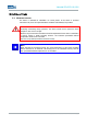
Industrial PCs IPC1100/1200 5 STARTUP Caution: The PC should be switched off before disconnecting plugs in order to avoid damage to electronic components! In order to avoid formation of condensation, the device should only be switched on once it has acclimated to the room temperature. Pay attention to the voltage permitted for the device. You should allow five seconds to pass between switching the device off and switching it back on. 5.
Industrial PCs IPC1100/1200 IPC1200 Note: Cable shielding of a data cable has to be connected to the plug connection casing (EMC). The interfaces have to be enabled in the embedded operating system and the matching drivers have to be installed to be able to use the interfaces. Pos : 20 /D atentec hni k/Inbetri ebnahme/Kabelmontage/Kabelmontage für OPC- Seri e / IPC 5100 / 5300 / 5500 / 1100 @ 0\mod_1158848147709_681.doc @ 797 @ 5.
Industria al PCs IPC1100/1200 5.5 EXTERNAL KEYBOARD D One mouse and on ne keyboard can be connected with both existing PS2 connectors. These connections are co olour coded for proper connection with this device e. PIN NUMBER SIGNAL NAME 1 Data 2 NC 3 GND 4 +5V 5 Clock 6 NC The control system m has a purple coloured 6-pin mini-DIN socket (PS S2) identified as “KEYB".
Industrial PCs IPC1100/1200 5.6 MOUSE The green coloured interface "MOUSE” is used to connect a mouse e. Check the mouse for compatibility before using it. PIN NUMBER SIGNAL NAME 1 Data 2 NC 3 GND 4 +5V 5 Clock 6 NC Note: The mouse must be b connected before switching the device on, sinc nce the mouse interface is initialised while booting! b If the mouse is connected during operat ation of this device, and the mouse was not ot connected during the booting process, it is not operable.
Industrial PCs IPC1100/1200 6 INTERFACES 6.1 6.2 INTERFACE CONFIGURATION INTERFACE IRQ ADDRESS COM1 4 3F8h COM2 3 2F8h COM3 11 03E8 LPT 7 378h SPANNUNGSVERSORGUNG 24 V DC Die Versorgungsspannung wird über eine Durchführungsklemme mit Schraubanschluss zugeführt (Bild zeigt Buchse im Gerät). PIN-NUMMER SIGNAL NAME 1 24V DC 2 PE 3 0 V DC Technische Daten des Netzteils • Leistungsaufnahme: Max.
Industrial PCs IPC1100/1200 6.3 230V AC POWER SUPP PLY An IEC connector is used as a power supply. The provided d cable should be used to connect the device. POWER SUPPLY UNITT TECHNICAL DATA • Power consu umption: Max. 60 Watts • Input voltag ge: 100…240V AC Note: The device's typicaal power input is listed in the "Technical Details" section.
Industrial PCs IPC1100/1200 6.5 NETWORK CONNECTION (RJ45) If the drivers required for functioning are installed on the device, the control system may be integrated in an Ethernet network supporting the 10/100 Mbit standard by using the Ethernet 10/100BaseT network connector. Specifications of this network topology must be observed in this case. You can install the drivers required for functioning from the enclosed service CD, should they not be installed on the device.
Industrial PCs IPC1100/1200 6.7 EXTERNAL DRIVES By default, no drive for removable media (CD/floppy disk) is integrated in the device. Additionally the system provides an USB interface, with which an external drive could be connected. In this case, you'd have to ensure that the equipment used is suitable for use in an industrial environment. Warning: Connecting or disconnecting of external drives during operation is inadmissible, since it cannot be excluded that the drive is in use at this point in time.
Industria al PCs IPC1100/1200 6.9 DVI INTERFACE The DVI Interface e is used to transfer analog and digital video signals. A DVI-I Cable is required to conne ect a digital display to the device. It is also posssible to connect a VGA display by using a suitable DVI-VGA adapter. Note: The DVI Interface ce is a Single Link Interface. The video signals are re transferred analog and digital.
Industrial PCs IPC1100/1200 7 DRIVES 7.1 HARD DRIVE / COMPACTFLASH (IDE INTERFACE) The choice of storage media depends on individual customer requirements. The following storage options are available: CompactFlash: This option implements a CompactFlash card with a capacity of at least 128 MB. The capacity should be chosen depending on the required operating system and additional programs to be installed. Hard drive/SSD: This option implements a 2,5" Festplatte mind. 30 GB (UDMA).
Industrial PCs IPC1100/1200 8 SOFTWARE & DRIVER INSTALLATION The device will be delivered with a pre-installed Windows operating system on request by the customer. The drivers required for this are already installed, and the operating system will be enabled by entering the licence information. Should an initial installation be required, please adhere to the following steps.
Industrial PCs IPC1100/1200 9 TECHNICAL DETAILS 9.1 COMPUTER TECHNICAL DATA The adsX module standard makes it possible to choose between different performance levels. IPC1000 series IPC1100 IPC1200 Computer Data Celeron® M 800 MHz ULV Processor Celeron® M 1,0 GHz ULV Pentium® M 1,6GHz Pentium® M 1,8GHz RAM 512MB up to 2GB RAM Chipset Intel® 855 GME Chipset Graphik memory¹ Mass Storage max. 32MB shared max. 64MB shared 2,5“ Automotive Festplatte min.
Industrial PCs IPC1100/1200 10 SERVICE AND SUPPORT The ads-tec company and their partner companies offer a comprehensive service and support to your customers providing a quick and professional support in case of any question with respect to ads-tec products and components. Since the devices from ads-tech company are also used by partner companies, these devices might be configured according to customer requirements.